Linear Up-Converters
Transmit-side and exciter-path conversion for moving IF or lower-band signals into the target RF output band.
View page
MICROWAVE FREQUENCY CONVERTERS
Microsource frequency converters provide spectrally translated RF/IF signal paths for radar, EW, SIGINT, and microwave test systems. Broad- and narrowband architectures are available, with filtering, gain conditioning, and harsh-environment packaging options.
Product overview
This page provides a family-level view of Microsource frequency converters. Use it to understand the broader conversion portfolio, then move into the dedicated up-converter or down-converter pages when the signal direction is already clear.
Translates a signal from one frequency range to another when the original band is not practical or effective for radiation, transport, or spectral analysis.
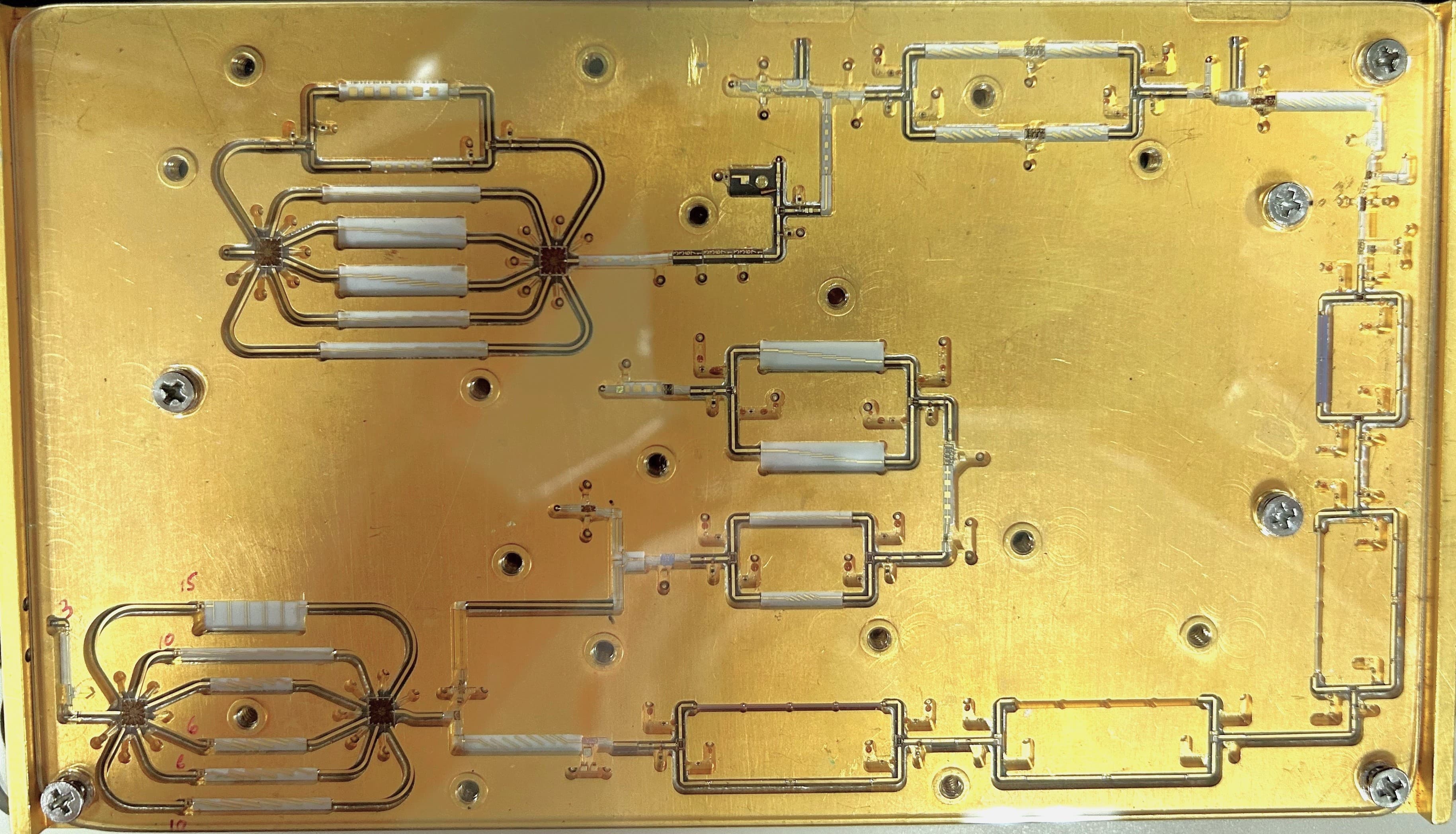
Uses a local oscillator and mixer architecture to shift RF and IF content while preserving signal structure within the intended bandwidth and linearity limits.
Choose the path
When the architecture is already defined, the fastest next step is usually to move into the dedicated page for the transmit-side or receiver-side path.
Architecture
Microsource frequency converters are available as wideband and narrowband designs, in both transmit (up-converter) and receiver (down-converter) configurations. Most use single-ended IF, with I/Q and single-sideband options available where needed.
Applications
Representative mission and subsystem contexts where translated RF/IF paths, bandwidth control, and spectral cleanliness matter.
Frequency translation within receiver and exciter chains for signal generation, processing, and band planning.
Up/down conversion for RWR, ESM, ECM, and jamming subsystems where spurious control and bandwidth matter.
Broadband conversion paths for collection, analysis, and signal routing architectures.
Converter modules for lab, bench, and system test environments requiring stable gain, flatness, and controlled spectral behavior.
System context
Frequency converters are typically used as translation stages between RF, IF, and local oscillator domains in radar, EW, and microwave systems.
Typical conversion paths (down- and up-conversion)
Representative performance
Measured performance varies by band, architecture, IF plan, and gain structure. These current catalog-backed examples show concrete wide-band up- and down-conversion configurations that match the refreshed dedicated product pages.
| Specification | Min | Max | Units |
|---|---|---|---|
| IF Output Frequency | 3.10 | 4.10 | GHz |
| RF Input Frequency | 2.0 | 18.0 | GHz |
| Channel Bandwidth (IBW) | — | 1.0 | GHz |
| Conversion Gain | — | 40 | dB |
| Noise Figure | — | 12 | dB |
| Residual Phase Noise at 100 MHz offset | — | -130 | dBc/Hz |
| IF Output P-1dB | — | 10 | dBm |
| Operating Temperature | -40 | +85 | °C |
| Specification | Min | Max | Units |
|---|---|---|---|
| IF Input Frequency | 3.1 | 4.1 | GHz |
| RF Output Frequency | 2 | 20 | GHz |
| Channel Bandwidth (IBW) | — | 1.0 | GHz |
| RF Output P-1dB | — | 10 | dBm |
| Conversion Gain | — | 10 | dB |
| Channel Bandwidth Flatness | — | 6.0 | dB pk-pk / 1 GHz IBW |
| Residual Phase Noise at 100 MHz offset | — | -130 | dBc/Hz |
| Operating Temperature | -40 | +85 | °C |
Values shown are representative examples from documented configurations in the MSI catalog and current released collateral. Detailed band plans, gain structures, LO schemes, and interface conditions remain program-specific.
Measured examples from the current WBRX and WBTX collateral help show that the overview page is anchored to real converter data rather than simulated placeholder plots.
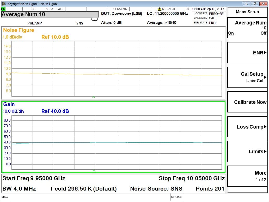
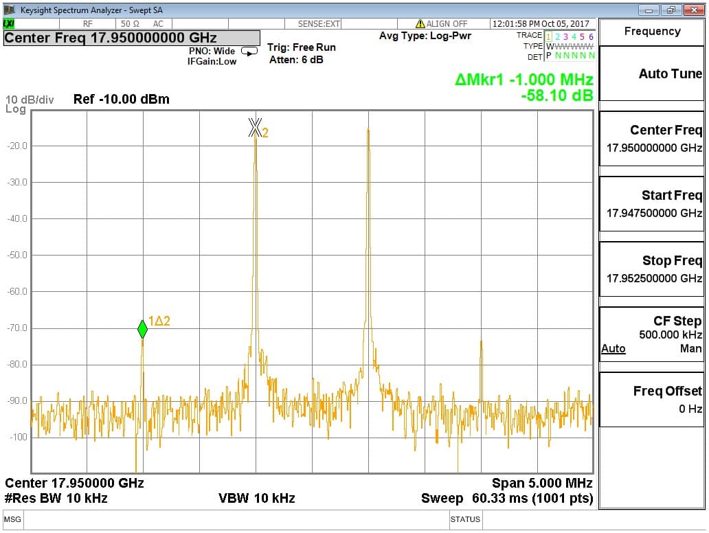
Measured data
Integrated filtering and careful frequency planning reduce unwanted products.
Flatness and bandwidth support complex modern radar and EW waveforms.
Architectures can be configured for the target signal chain and platform constraints.
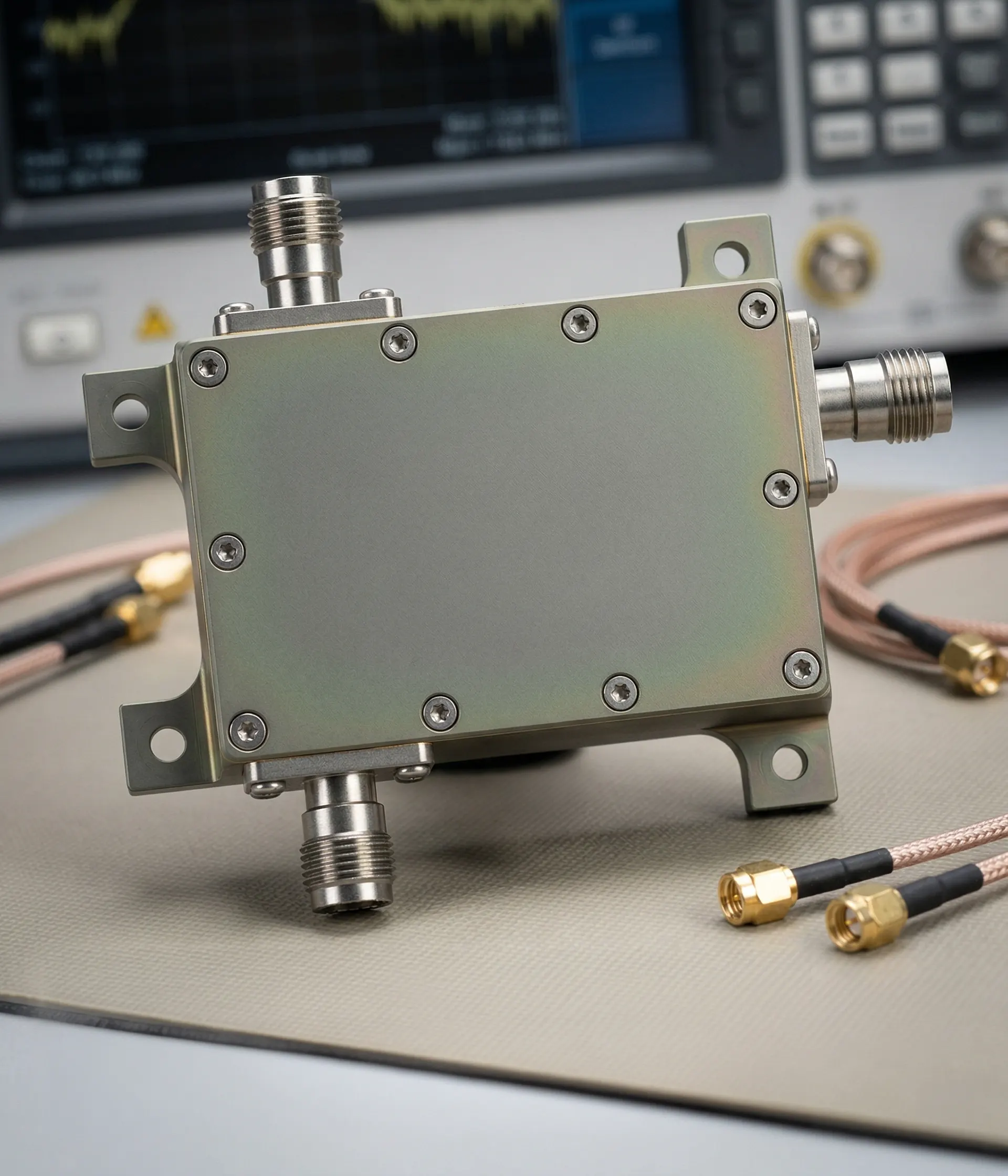
Integration
Mechanical and interface options aligned with subsystem integration requirements.

NEXT STEP
Share your RF band, IF plan, bandwidth, gain, and platform requirements to identify an appropriate converter architecture.