
PERMANENT MAGNET YTOs FOR LOW-NOISE MICROWAVE SYSTEMS
Wideband YIG Oscillators Optimized for Low Phase Noise and Reduced Power
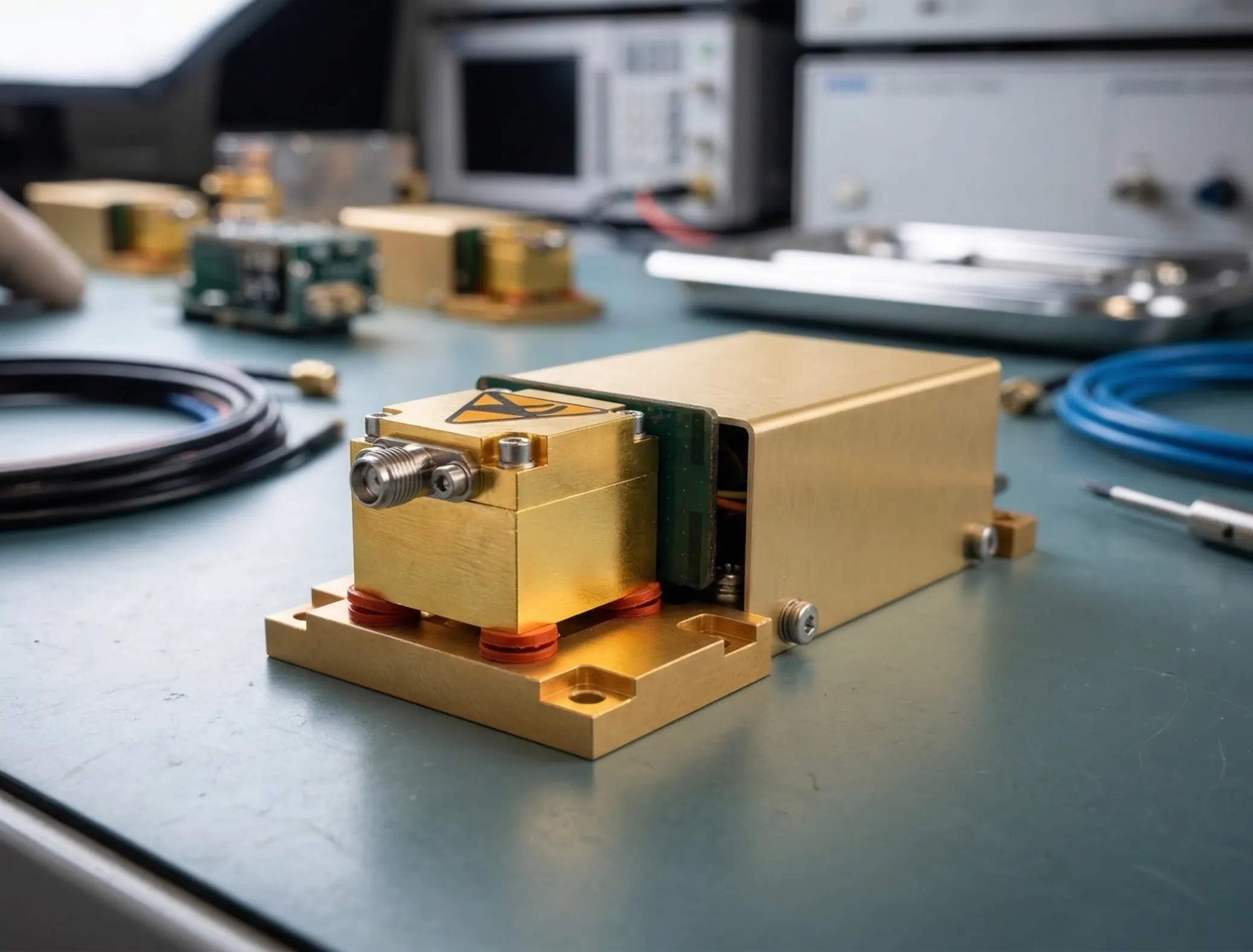
Permanent magnet YTOs designed for radar, EW, and signal generation systems requiring low phase noise, reduced power consumption, and compact integration.
Product overview
Operational overview
What a YTO does
Generates a tunable microwave signal over a defined frequency range, serving as a stable source for RF and microwave systems.
How it tunes
Frequency is controlled by adjusting the magnetic field applied to the YIG resonator, enabling continuous analog tuning across the operating band.
Why it's used
- Low phase noise for high-performance signal chains
- Wide, continuous tuning range without band switching
- Stable, repeatable output under varying operating conditions
Differentiation
Why Permanent Magnet YTOs
Permanent magnet bias introduces a fixed magnetic field component, reducing the current required from the tuning coil. This directly impacts size, power consumption, and thermal behavior of the oscillator.
- Reduced tuning current via magnetic biasing (bidirectional operation)
- Smaller coil geometry enabling more compact assemblies
- Lower power consumption compared to electromagnet-only designs
- Improved thermal stability and reduced drift sensitivity
- Better alignment with SWaP-constrained system requirements
Applications
Where YTOs are used
Representative mission contexts where LO purity, agility, and repeatability matter.
Radar Systems
Stable LO performance across modes—supports coherent processing and fast frequency-agile operation.
Electronic Warfare (EW)
Maintains spectral purity during rapid retuning—reduces detection and interference risk in dynamic environments.
SIGINT / ELINT
Low phase noise across wide bands—preserves sensitivity in broadband collection systems.
Test & Measurement
Repeatable, low-noise signal generation—supports calibration, validation, and lab-grade reference use.
Representative performance
Representative Performance (11.7–13.0 GHz Configuration)
Representative performance for permanent magnet YTO (11.7–13.0 GHz configuration). Measured on production units under controlled conditions.
| Specification | Min | Max | Units |
|---|---|---|---|
| Frequency Tuning Range | 11.7 | 13.0 | GHz |
| Frequency Accuracy @ +25° C | — | ± 10 | MHz |
| Frequency Drift v. Temperature | — | 18.2 | MHz |
| Frequency Step Size – nominal per bit (4096b range) | 317.4 | — | kHz/b |
| Frequency Settling Time to within ±10 MHz | — | 100 | ms |
| Frequency Pulling into 12 dB Return Loss | — | 1 | MHz |
| Frequency Pushing | — | 1 | MHz/V |
| RF Performance | |||
| RF Output Power Setting @ +25° C | 10 | 14 | dBm |
| RF Power Flatness over Tuning Range and Temperature | — | ± 1 | dB |
| FM Tuning | |||
| FM Coil Tuning Voltage Range | -10 | 10 | Volts |
| Frequency Deviation | -25 | 25 | MHz |
| FM Load Impedance | 1 | — | kΩ |
| FM Tuning BW (3 dB) | — | 2.0 | MHz |
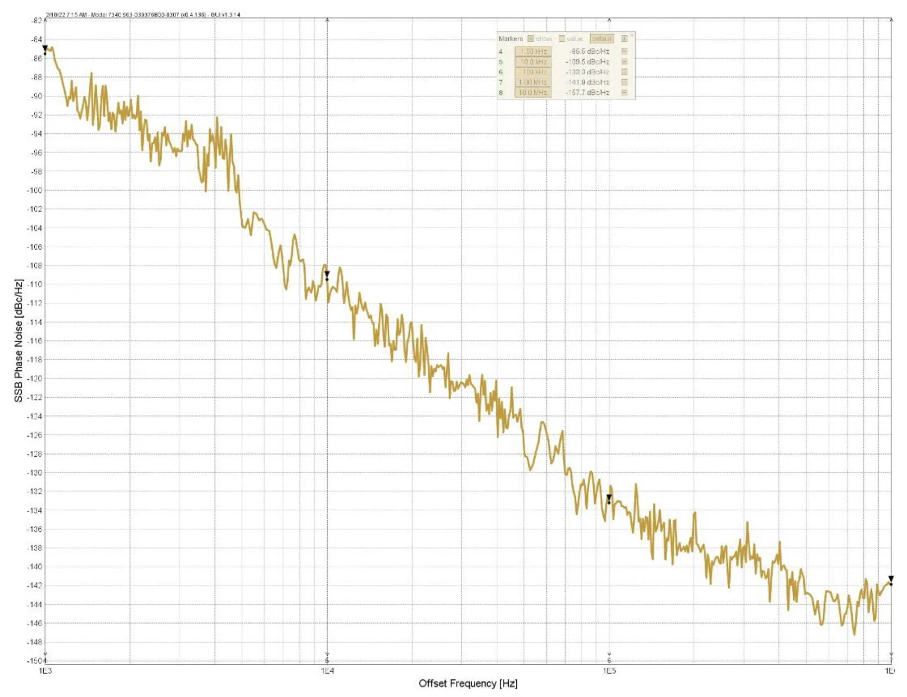
| Phase Noise | |||
| Phase Noise at Δ1 kHz Offset from Carrier | — | -30 | dBc/Hz |
| Phase Noise at Δ10 kHz Offset from Carrier | — | -87 | dBc/Hz |
| Phase Noise at Δ100 kHz Offset from Carrier | — | -122 | dBc/Hz |
| Phase Noise at Δ1 MHz Offset from Carrier | — | -140 | dBc/Hz |
| Phase Noise at Δ10 MHz Offset from Carrier | — | -150 | dBc/Hz |
| Spurious and Harmonics | |||
| RF Output Spurious | — | -70 | dBc |
| RF Output 2nd Harmonic | — | -12 | dBc |
| RF Output 3rd Harmonic | — | -20 | dBc |
| Power and Environment | |||
| Current for Input Voltage of +15V ± 1V | — | 170 | mA |
| Current for Input Voltage of -15V ± 1V | — | 200 | mA |
| Current for Input Voltage of +5V ± 1V | — | 150 | mA |
| Operating Temperature Range | 0 | +70 | °C |
Values shown are representative. Detailed performance, environmental limits, and interface conditions are available upon request.
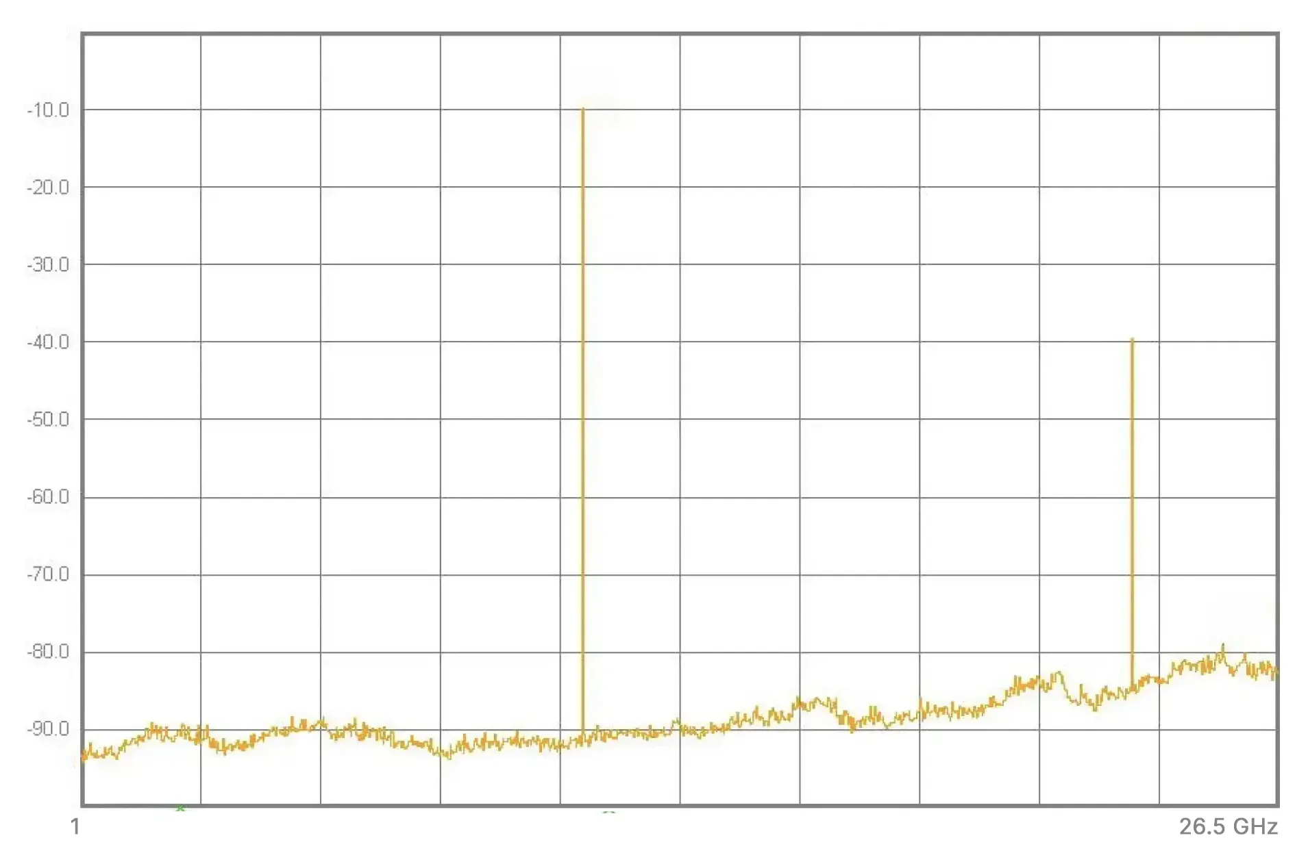
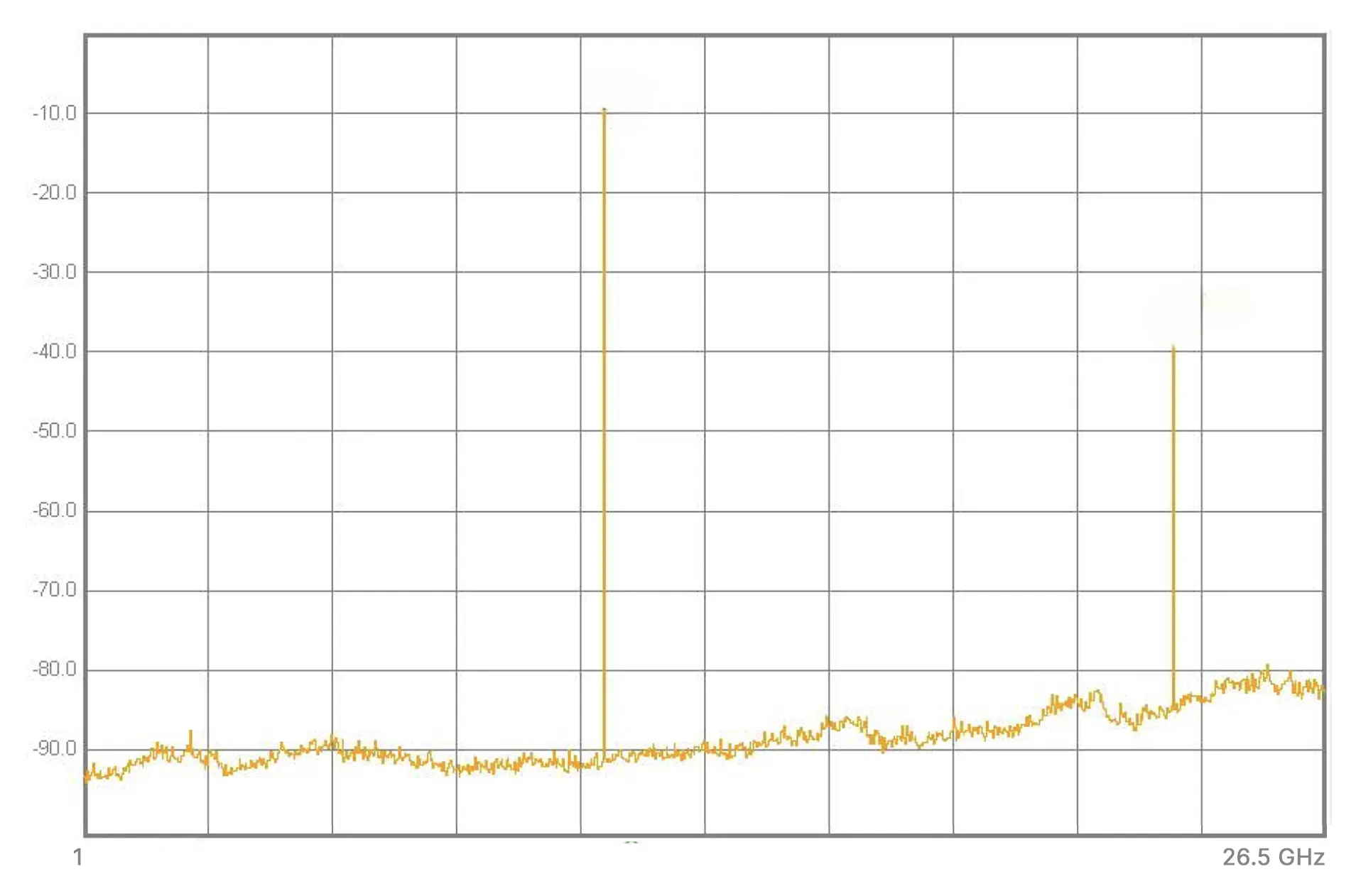
Spurious Performance
Broadband spurious search (Keysight swept spectrum analyzer) at 11.7 GHz and 13.0 GHz tune points.
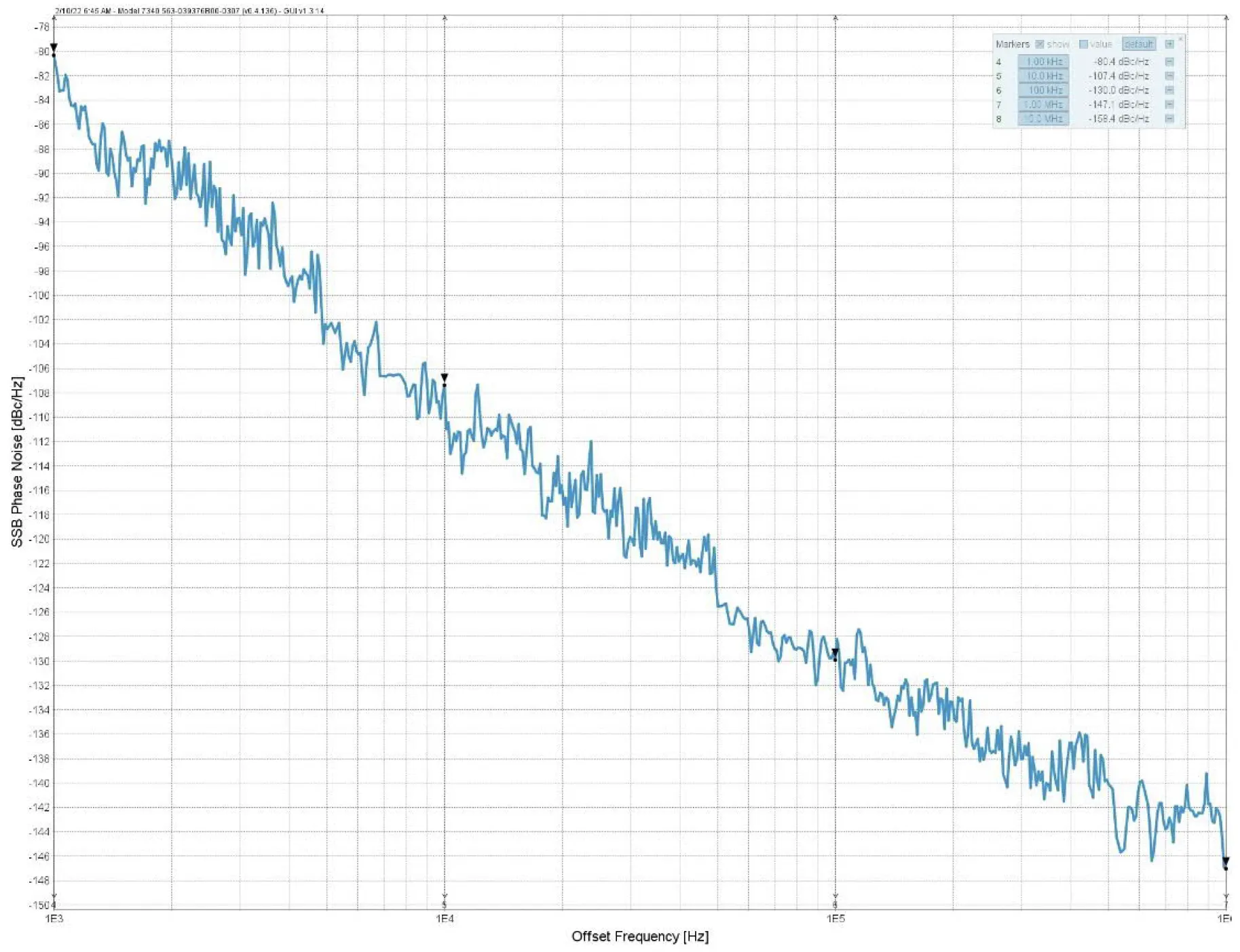
Phase Noise Performance
Single-sideband phase noise vs. offset frequency at representative tune points.
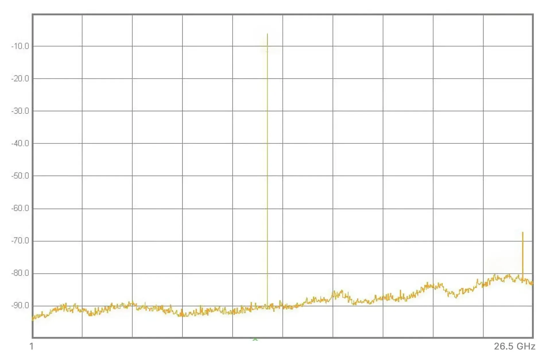
HARMONIC PERFORMANCE
Harmonic Performance
Measured harmonic output at representative tuning points using a swept spectrum analyzer.

Integration
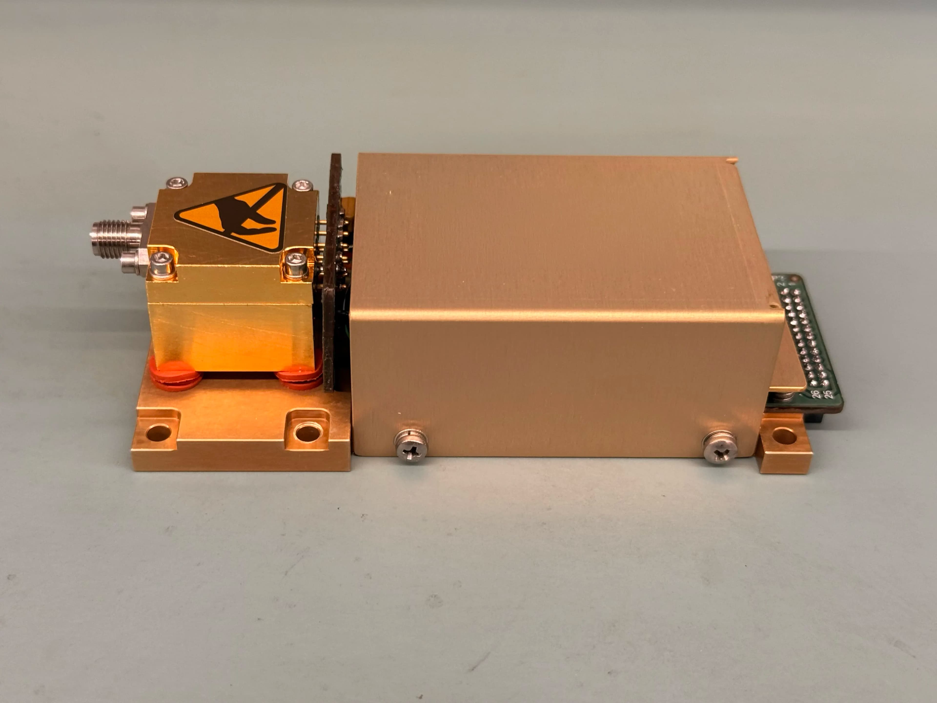
Form factor and hardware
Mechanical and interface design aligned with subsystem integration requirements.
- Machined aluminum housing with chem-film finish (MIL-DTL-5541)
- SMA or SMPM RF interfaces depending on configuration
- Integrated driver and control electronics
- Designed for direct integration into RF subsystems
System context
Where it fits in your system
YIG oscillators are typically used as precision local oscillators and signal sources within RF and microwave systems:
- Local oscillators in frequency conversion chains
- Precision signal sources for test and measurement systems
- Frequency-agile sources in EW and SIGINT platforms
Typical RF Signal Chain Integration

Need a stable, low-noise microwave source?
Share your frequency plan, tuning range, and environmental requirements — we will align you to a representative configuration and data package.