DIELECTRIC RESONATOR OSCILLATORS
Dielectric Resonator Oscillators (DROs)
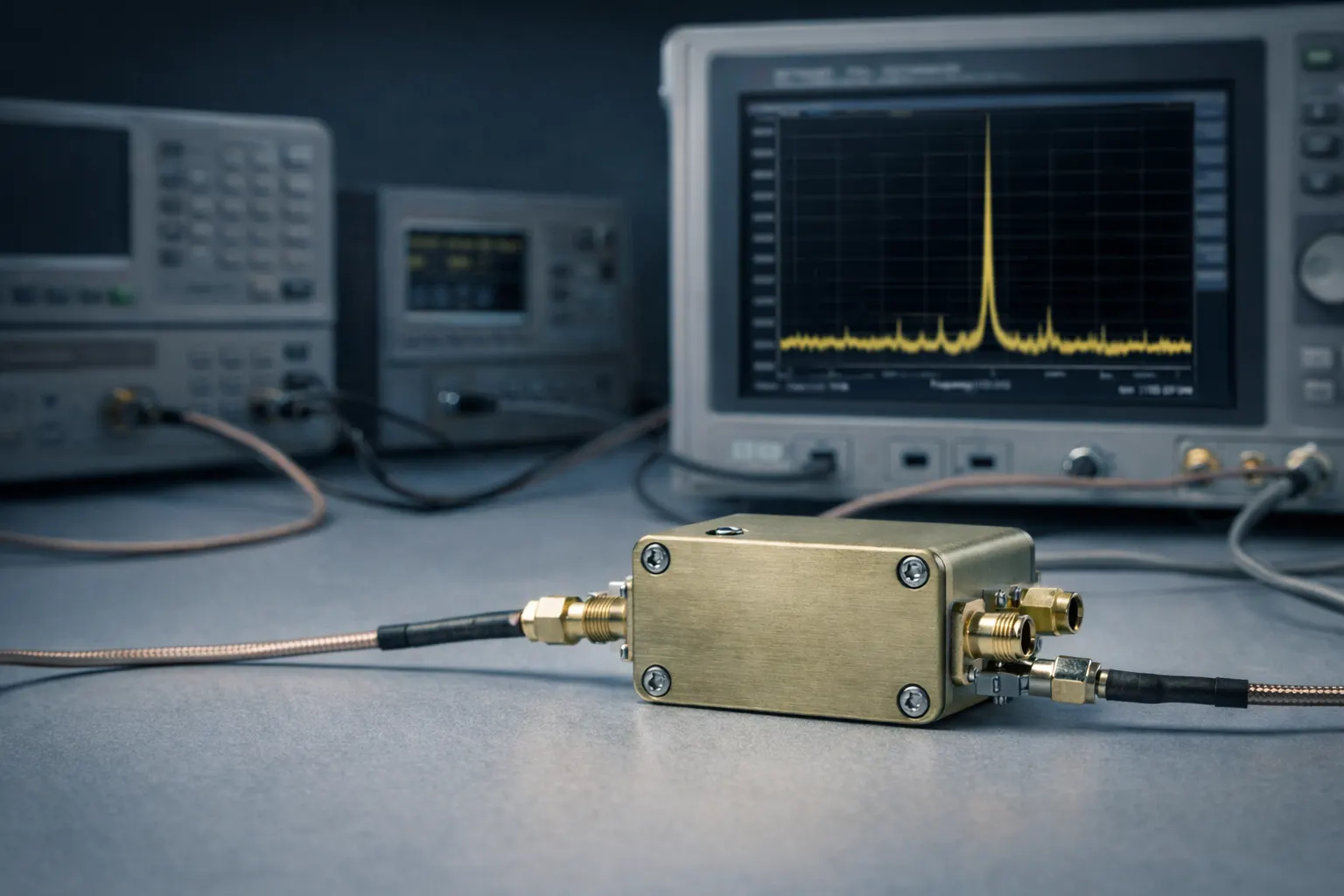
Low phase noise, frequency-stable microwave sources for radar, communications, and precision RF systems.
Microsource DROs address applications that need a small, light, low–DC-power source with high stability and low phase noise—without the wide electronic tuning range of a YIG-tuned oscillator (YTO) or VCO-based synthesizer. Where a fixed or narrow-tuning LO or reference is the right fit, a DRO is often the simplest path.
Microwave sources
Engineered for stable microwave source applications
Dielectric Resonator Oscillators (DROs) are used where a small, light, low DC power consumption, highly stable frequency source is needed, and where only a relatively small electronic tuning range is required—they do not provide the broad tuning range of a VCO or YTO. Microsource DROs use three-terminal active devices (e.g., HBTs and MESFETs) tuned for high efficiency and low noise, with designs intended for harsh environments. Hermetic and non-hermetic builds are available; RF/DC connection and finish options vary by configuration.
- Fixed or narrow-tuning roles: LO, reference, and stable source applications where wide agility is not required.
- Contrast with YTO/synthesizer families: trade tuning span for simplicity, SWaP, and often straightforward subsystem integration.
- Interconnect and environmental options are specified at the program level—see representative packaging notes for G-DRO-10-12-000.
Capabilities
What we deliver
Behavior is resonator- and band-specific.
Low Phase Noise Performance
High-Q dielectric resonator stabilization supports strong close-in and far-from-carrier performance for a fixed/narrow-tuning source—see published offsets for G-DRO-10-12-000.
High Frequency Stability
Intended as a highly stable frequency source with defined accuracy, drift, pulling, and pushing characteristics per datasheet.
Narrow Tuning / Fixed-Frequency Operation
Electronic and mechanical tuning ranges are modest by design—not a substitute for YTO- or synthesizer-class tuning breadth.
Efficient Microwave Source Design
Active devices are selected and tuned for high efficiency and low noise in a compact microwave oscillator realization.
Harsh-Environment Packaging Options
Designed for harsh environments; hermetic and non-hermetic constructions are available depending on program requirements.
Flexible RF and DC Interconnect Options
RF/DC connection and finish options vary—connector families and pin finishes are specified to match platform interfaces.
Architecture
Implementation and differentiation
A DRO uses a dielectric resonator to stabilize a microwave oscillator core. Microsource implementations emphasize efficient, low-noise active devices and packaging suited to deployed hardware.
Dielectric resonator controlled oscillation
The dielectric resonator sets the high-Q stabilizing element that anchors oscillation frequency—supporting spectral purity relative to a free-running wideband VCO without the electromechanical tuning mechanism of a YTO.
Efficient three-terminal active device design
Microsource DROs use three-terminal active devices such as HBTs and MESFETs, tuned for high efficiency and low noise.
Fixed or narrow-tuning source architecture
DROs fit where a relatively small electronic tuning range is acceptable. They are not specified to deliver VCO- or YTO-like tuning span; requirements should be stated in MHz-of-tune, pulling/pushing budgets, and environmental limits.
DRO vs YTO / VCO / synthesizer use case
Versus a YTO: less tuning range, but well matched to stable LO and reference paths when agility is secondary. Versus a synthesizer: a simpler fixed/narrow source in many cases—lower control complexity when step/hop programming is not required. Versus wideband VCO approaches: prioritize stability and noise in a narrow band rather than octave tuning.
Model numbering
Designations follow G-DRO-XX-YYY, where XX is the approximate frequency range in GHz (leading zero below 10 GHz) and YYY is a Microsource-assigned option number.
G-DRO-10-000 — example: 10 GHz DRO, original option
Applications
Where DROs fit
Practical LO and stable-source contexts—especially when tuning span is modest and stability/noise dominate the requirement.
Local oscillator generation
Drive mixers and converters with a stable tone when the plan does not require wideband agility.
Radar systems
Coherent LO and reference paths where narrow tuning and phase noise matter more than octave coverage.
Electronic Warfare
Stable sources in RF chains where architecture calls for a compact, efficient fixed-frequency tone.
Satellite communications
Payload- and ground-adjacent LOs with disciplined spectral behavior and defined environmental limits.
Test & measurement systems
Reference-quality sources for bench and subsystem test—not a substitute for a full bench synthesizer when sweep/step agility is required.
Frequency conversion chains
Pairs naturally with Microsource converters and multipliers as the stable LO anchor in the chain.
Configurations
Representative configurations
Patterns typical of Microsource offerings—specific part numbers, screening, and interfaces are program-specific.
Fixed-frequency DRO modules
Minimal tuning: set-and-forget LO and reference roles with defined environmental qualification.
Narrow electronic tuning DROs
Small tuning range with electronic and mechanical trim as documented in representative specs.
Stable LO source modules
Packaged for chassis integration with RF and DC interfaces selected for the platform.
Custom connector / finish configurations
RF/DC connection and finish options vary; align to mating hardware and corrosion requirements.
Hermetic and non-hermetic builds
Select hermetic or non-hermetic construction based on leak rate, outgassing, and lifetime environment.
DRO-based subsystems
Can be integrated with conditioning and distribution in larger microwave assemblies when the program warrants.
Representative configuration
G-DRO-10-12-000
Published electrical and environmental data for MICROSOURCE DIELECTRIC RESONATOR OSCILLATOR G-DRO-10-12-000. Nominal center frequency range describes where this class may operate; see footnote regarding tuning range vs. band of operation.
| Parameter | Value |
|---|---|
| Identification | |
| Model | G-DRO-10-12-000 |
| Frequency | |
| Nominal center frequency range | 10.0–12.0 GHz |
| Frequency accuracy @ +25 °C | ±1 MHz |
| Frequency drift vs. temperature | 2.5 MHz |
| Electronic tuning sensitivity | 2.0 nominal MHz/V |
| Mechanical tuning range | 50 MHz |
| Frequency pulling into 12 dB return loss | 1 MHz |
| Frequency pushing | 1 MHz/V |
| RF output | |
| RF output power setting @ +25 °C | 0 to +4 dBm |
| RF power variation vs. temperature | ±1 dB |
| Electronic tuning voltage range | 0 to 17 V |
| Tuning port capacitance | 5 pF |
| FM tuning BW (3 dB) | 1.0 MHz |
| Phase noise (10.5 GHz carrier) | |
| Phase noise @ 1 kHz offset | −50 dBc/Hz |
| Phase noise @ 10 kHz offset | −78 dBc/Hz |
| Phase noise @ 100 kHz offset | −105 dBc/Hz |
| Phase noise @ 1 MHz offset | −135 dBc/Hz |
| Phase noise @ 10 MHz offset | −155 dBc/Hz |
| Spectral | |
| RF output spurious | −70 dBc |
| RF output 2nd harmonic | −25 dBc |
| RF output 3rd harmonic | −15 dBc |
| Dynamics & power | |
| Settling time to within 10 kHz | 250 nominal µs |
| Current for input voltage +8 V ±1 V | 150 mA |
| Operating temperature range | −40 to +85 °C |
This is a range of frequencies over which this class of DRO may operate. This is not the tuning range specification.
Representative configuration shown. Final performance, tuning behavior, and packaging options may vary by frequency and application.
Measured data
Typical performance (representative figures)
Catalog-backed measured plots for representative G-DRO-10-12-000 tune points, including phase noise, amplitude noise, spurs, and harmonics.
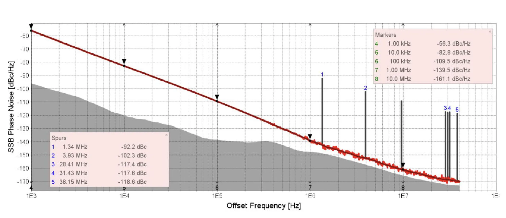
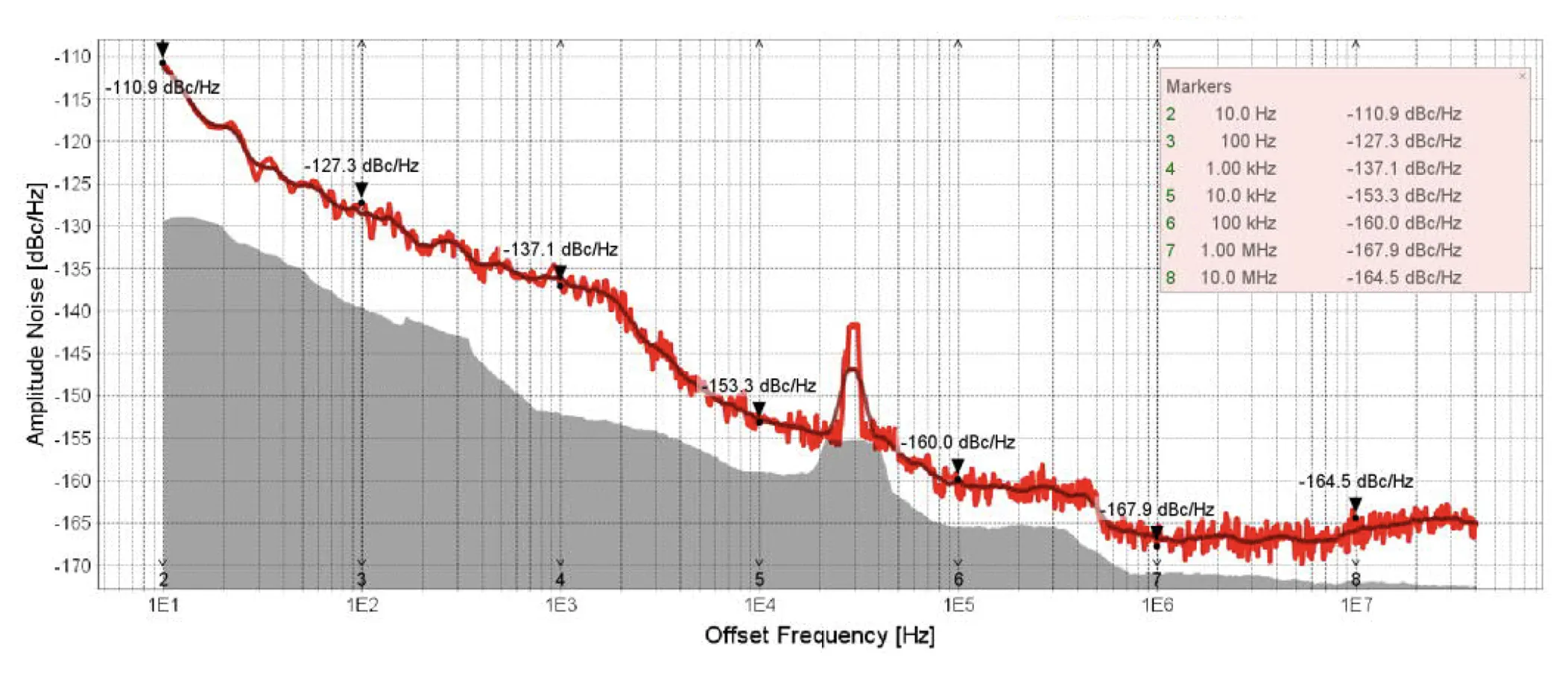
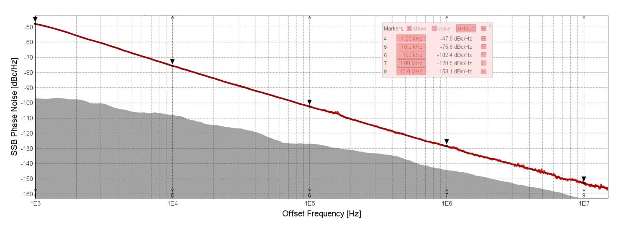
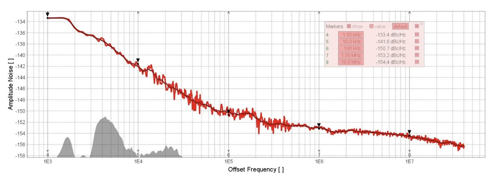
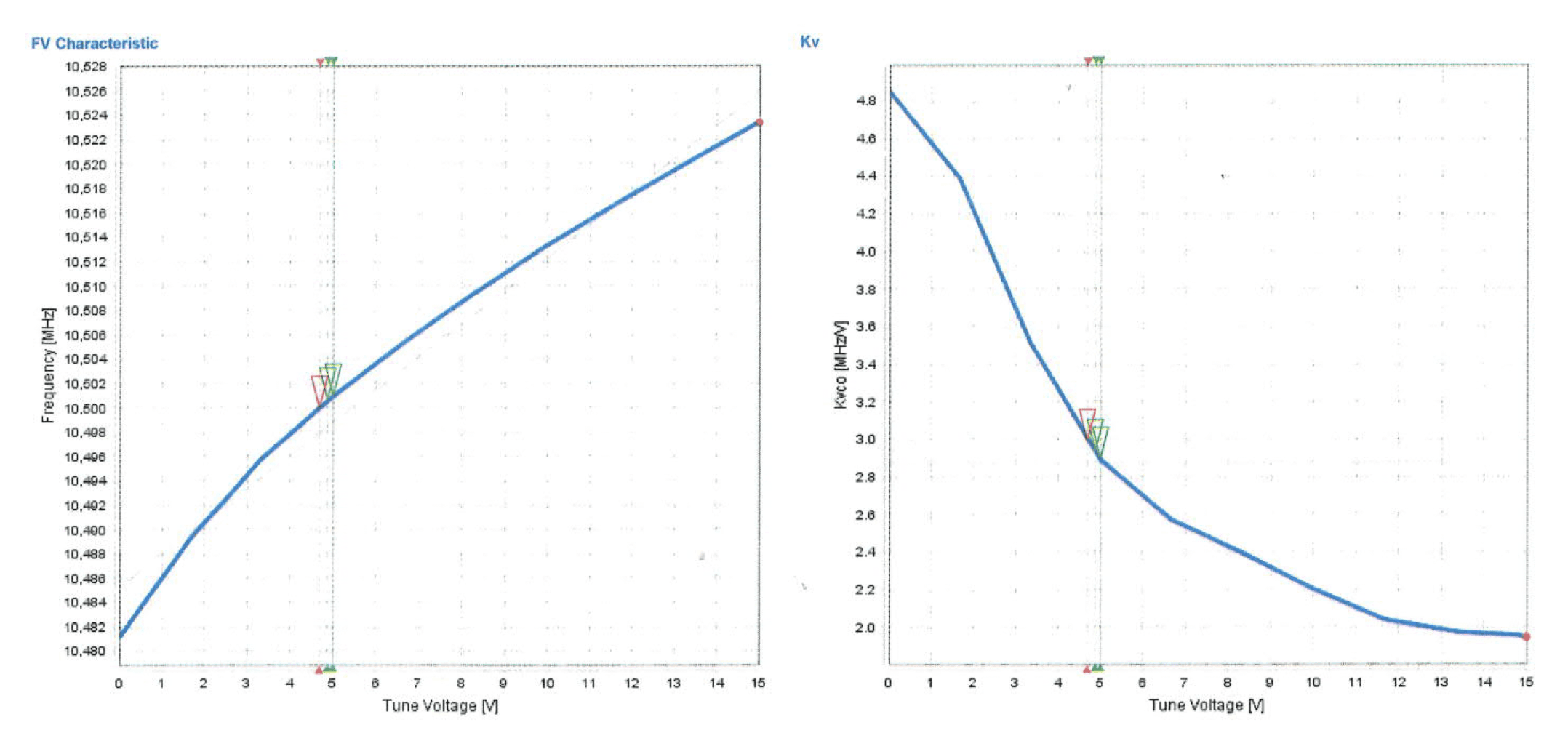
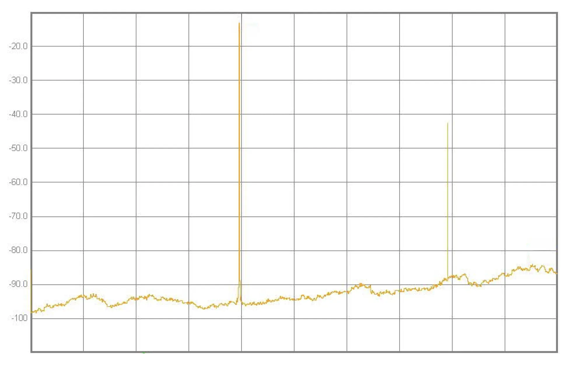
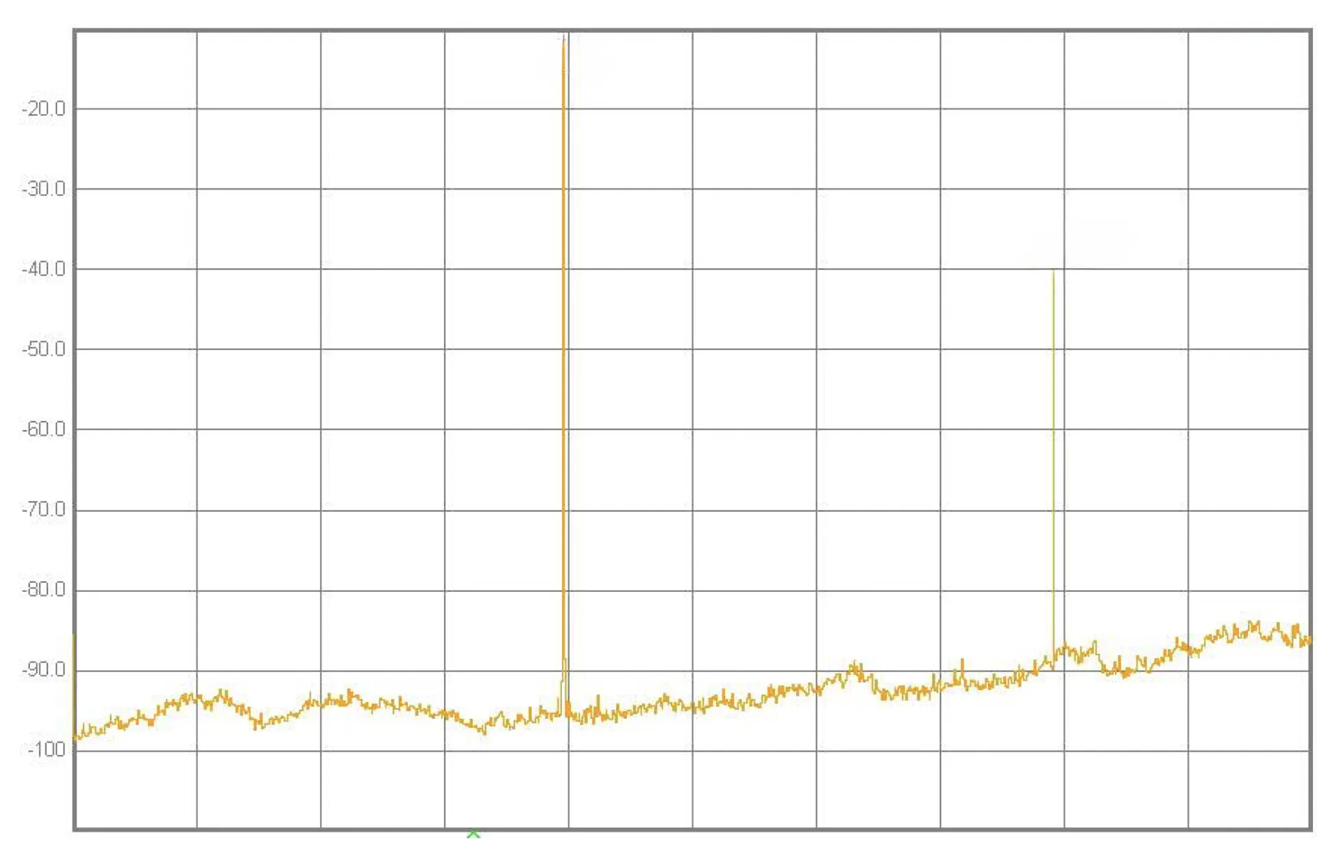
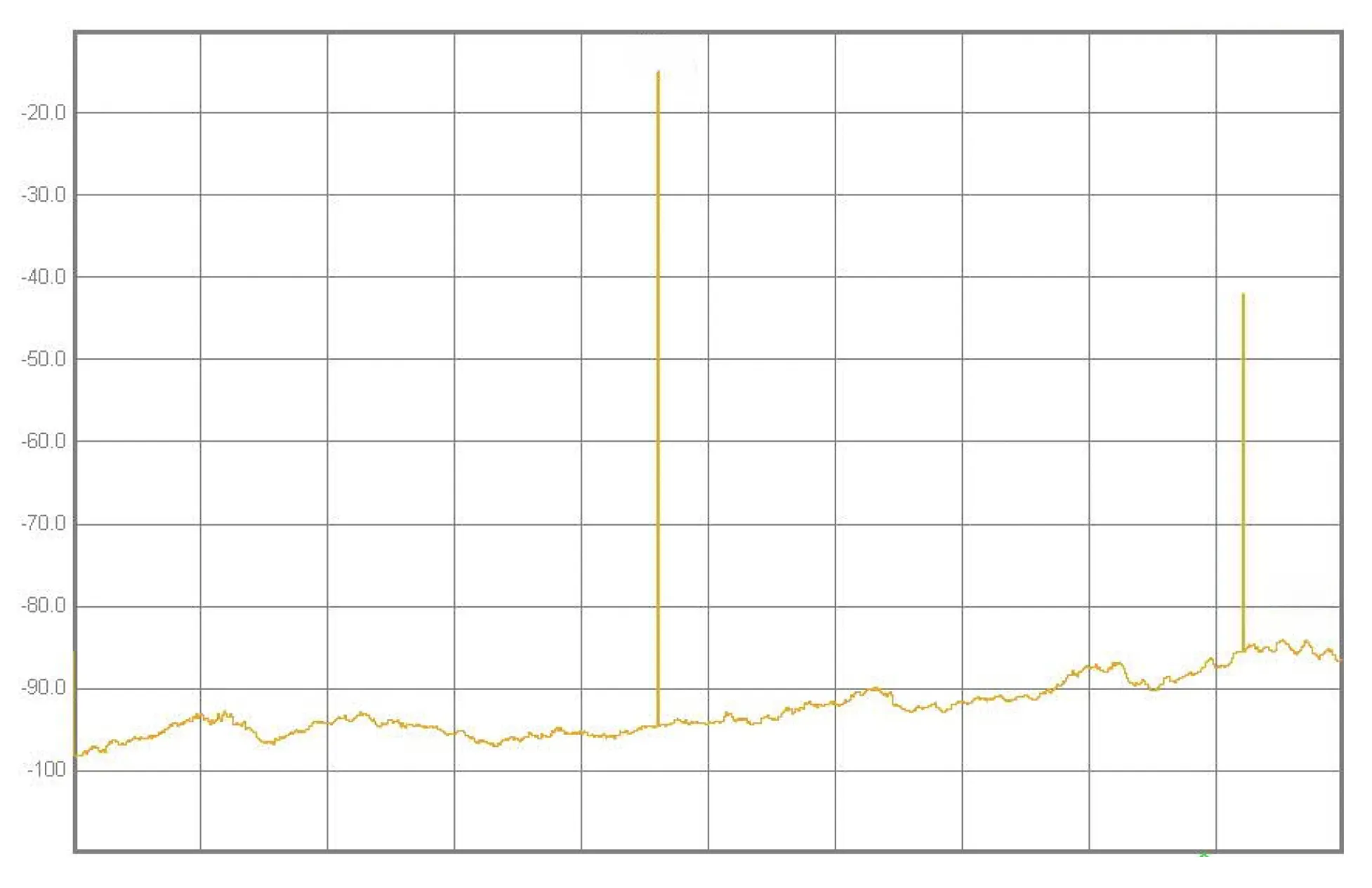
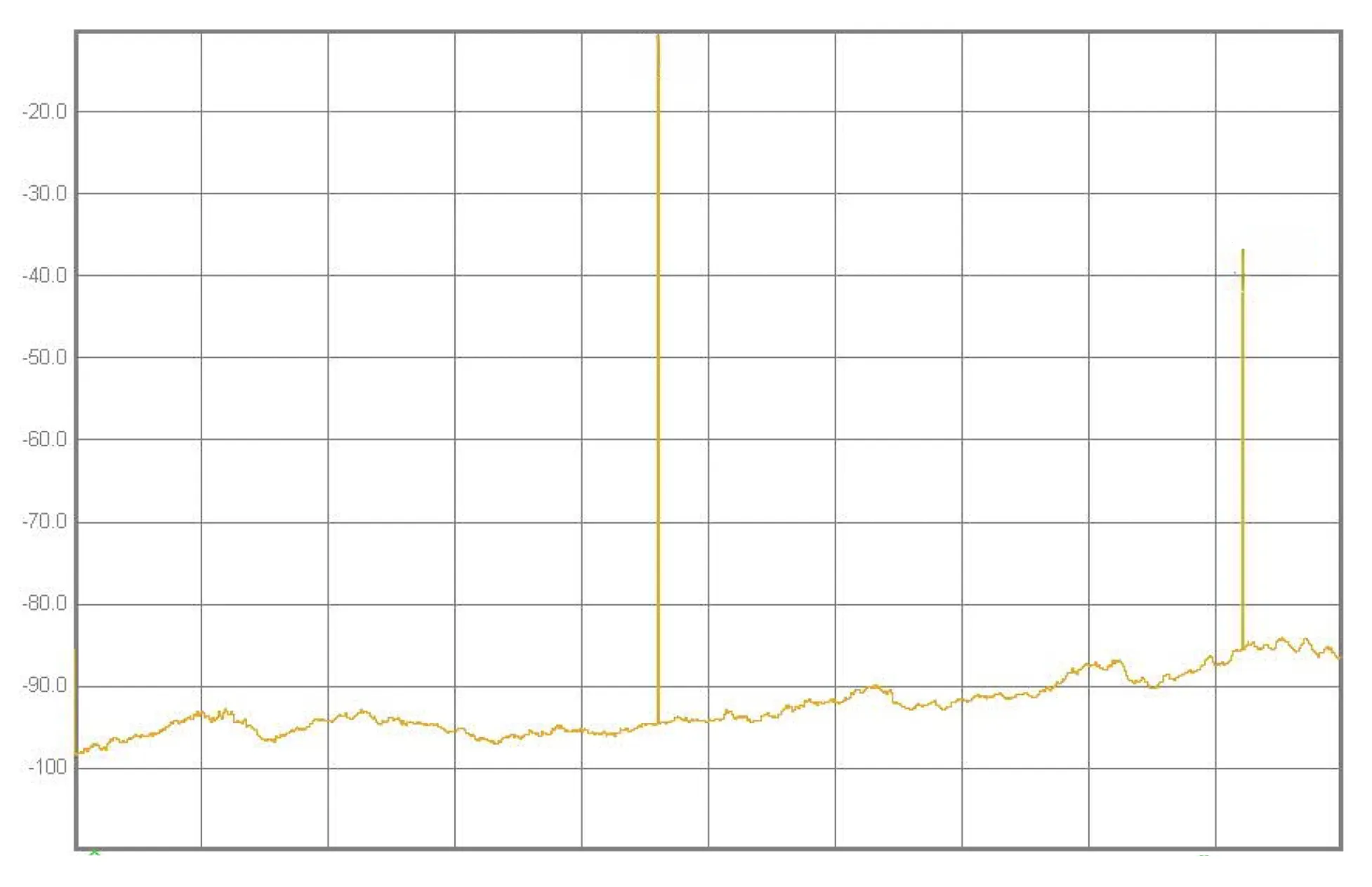
Representative measurements for G-DRO-10-12-000 from the MSI catalog. Final limits and screening follow the approved program documentation.
Architecture fit
DRO vs YIG oscillator vs synthesizer
High-level guidance for source selection—final choice depends on band plan, noise budget, agility, and control architecture.
| Characteristic | DRO | YIG oscillator | Synthesizer |
|---|---|---|---|
| Tuning range | Fixed / narrow electronic and mechanical trim | Wide tunable band (YTO-class agility) | Programmable steps / hops per design |
| Stability | High for narrow-band resonator-stabilized source | Strong; band-set dependent | Reference- and loop-dependent |
| Phase noise | Low—excellent for fixed/narrow LO roles (see typical measured plots) | Very good; ultimate noise vs. tuning tradeoffs | Depends on VCO/YTO architecture and loop |
| Complexity | Lower—oscillator module vs. full synthesizer | Medium—tuning driver and bias complexity | Highest—reference, loop, and control stack |
| Best use case | LO / reference / stable source without wide agility | Swept / agile microwave sources needing wide tune | Precision frequency control and step-based operation |
Packaging
Representative packaging and material notes
Mechanical and materials data for G-DRO-10-12-000—confirm details on your program datasheet.
- Dimensions: 1.5" (L) × 1.0" (W) × 0.60" (H), excluding mechanical tuning element and RF connector.
- DRO housing / inner cover: aluminum alloy 6061, chemical conversion coated per MIL-DTL-5541F.
- Outer cover: aluminum alloy 4047, chemical conversion coated per MIL-DTL-5541F.
- RF connector: SMA female, 2.92 mm female, SMPM, or equivalent.
- DC pins: 0.03" dia. soft electroless gold over Kovar (Fe-Ni-Co alloy) or equivalent.
Why Microsource
The right source architecture for the mission
Microsource brings long microwave heritage across DROs, YIG oscillators, synthesizers, multipliers, and converters—so source choice is an engineering decision, not an afterthought. We support harsh-environment packaging, screening options, and custom interconnect when programs require it, and we align oscillator class to real platform constraints.
Related solutions
Adjacent product families
DROs complement tunable and programmable sources elsewhere in the line card.
- YIG OscillatorsWideband YTO-based tunable sources.
- Microwave Frequency SynthesizersProgrammable LO and signal generation subsystems.
- Frequency ConvertersUp/down conversion around stable LOs.
- Frequency MultipliersChain extension from references and DRO tones.
- Integrated Microwave AssembliesSubsystem integration and multi-function assemblies.

NEXT STEP
Discuss your microwave source requirements
Talk with Microsource about fixed-frequency, narrow-tuning, and custom oscillator solutions for demanding RF and microwave systems.