NON-LINEAR FREQUENCY MULTIPLIERS
Non-Linear Frequency Multipliers
Broadband microwave frequency extension for local oscillator chains, signal generation, and high-frequency subsystem design.
Use a multiplier when direct generation at the target frequency is not practical. Microsource modules extend a lower-frequency drive into higher microwave or mm-wave bands while prioritizing low residual phase noise, sub-harmonic suppression, and broadband coverage.
Signal chains
Engineered for high-frequency signal generation paths
Frequency multipliers are used when a fundamental source alone cannot economically or spectrally deliver the required output tone. They are standard building blocks in local oscillator chains, where broadband operation and low residual phase noise preserve system noise budgets. Suppressing sub-harmonics and out-of-band products is a first-order design concern, alongside passband flatness and usable output power. Depending on efficiency targets, implementations may emphasize balanced passive structures or add active stages where conversion gain matters.
- Extension, not replacement: multiply from a stable drive when direct synthesis or fundamental sources are impractical at the target band.
- LO-centric thinking: multipliers commonly sit between a reference or tunable source and mixers, converters, and distribution.
- Architecture tradeoffs: multiplication modulus, filtering depth, and passive vs. active stages are balanced against bandwidth, suppression, and output power.
Capabilities
What we deliver
Multiplier behavior is band- and plan-specific—representative configurations illustrate the engineering trade space.
Broadband Frequency Extension
Microwave multiplier cores that cover wide fractional bandwidths when the plan allows, using balanced diode architectures and broadband baluns to support multi-octave or multi-band operation.
Low Residual Phase Noise
Designs intended to preserve the quality of the drive—multiplication adds residual noise in a way that must be managed alongside filtering and output conditioning.
Sub-Harmonic Suppression
Harmonic and sub-harmonic products are addressed through topology and, where needed, switched-band band-pass filtering to keep the output spectrum clean.
Integrated Filtering
Filtered output chains—including switched band-pass paths—help isolate the desired multiplied product from adjacent spurious and harmonic content.
Multiple Multiplication Factors
Different multiplication moduli (x2, x3, and combined multi-band paths) are used to match input frequency, output band, and efficiency requirements.
Harsh-Environment Packaging Options
Hermetic and non-hermetic builds, connector families, plating and finish choices, and screening options align to platform environmental and interface requirements.
Architecture
Implementation and building blocks
Microsource frequency multipliers combine nonlinear microwave structures with balanced excitation, filtering, and—when needed—active gain to deliver usable broadband power with controlled spectral content.
Balanced diode multiplier architectures
Many designs use balanced diode structures to improve symmetry, drive efficiency, and rejection of unwanted products relative to single-ended approaches.
Broadband balun structures
Baluns convert single-ended drive to balanced excitation across the multiplier core, supporting broadband operation over the intended input band.
Filtered output chains
Switched band-pass filtering and post-multiplier filtering mitigate sub-harmonics and spurious emissions, especially when the output band spans multiple octaves or adjacent services are sensitive to leakage.
Active multiplier approaches
When conversion efficiency and output power are limiting, active multiplier stages can be employed to recover loss and meet amplitude targets while maintaining the overall spectral plan.
Family model numbering
Designations follow G-MFXA-XX-YY-ZZZ: A is the frequency multiplication modulus; XX and YY are the lowest and highest output frequency in GHz (leading zero below 10 GHz); ZZZ is a Microsource-assigned option number.
Example: G-MFX3-20-50-000 — x3 multiplier covering 20–50 GHz output (illustrative of the naming scheme).
Applications
Where multipliers are used
Typical roles for broadband multiplier modules in deployed and test hardware.
Local Oscillator Chains
Extending a fundamental or synthesizer drive into higher bands for mixer and converter LO ports.
Radar Systems
LO generation and extension for coherent and imaging radar front ends where band plan and spur budgets are strict.
Electronic Warfare
Fast-set, broadband multiplier paths that support threat-relevant bands when integrated with sources and conditioning.
Satellite Communications
Ground and payload-adjacent chains where multiplied LOs must coexist with tight link budgets and spurious limits.
Frequency Conversion Paths
Upstream of mixers and converters—multipliers raise the tone before translation or distribution.
High-Frequency Test Subsystems
Bench and production test setups that need stable multiplied tones for stimulus and reference paths.
Configurations
Representative configurations
Common offering patterns—specific interfaces, screening, and frequency plans are defined per program.
x2 Broadband Multipliers
Doubler-focused modules for octave-style extension when the input band and spur plan support a single modulus.
x2 / x3 Multi-Band Multipliers
Configurations that switch multiplication path or input sub-band to cover wider output spans with controlled drive levels.
Filtered LO Extension Modules
Multiplier chains with integrated band-pass filtering for LO roles where adjacent-channel rejection is critical.
Active Multiplier Chains
Passive multiplier cores followed by or combined with active stages when output power and conversion efficiency drive the requirement.
Packaged Microwave / mm-Wave Assemblies
Module-level enclosures with defined RF and DC interfaces for chassis integration and environmental qualification.
Custom Connector / Finish / Screening Options
SMA, 2.92 mm, SMP-class interfaces, plating and conversion coatings, and program-specific screening as required.
Representative configurations
Electrical summary
Side-by-side comparison of two documented representative multiplier configurations. Multiplication range, flatness, suppression, and output power must be read together—they trade with filtering depth and bandwidth.
| G-MULT-20-40-000 | |
|---|---|
| Multiplication | x2 |
| RF input | 10.1–20.0 GHz |
| RF output / bands | Band 1: 20.2–25.4 GHz; Band 2: 25.4–32.0 GHz |
| P_in | −10 to 0 dBm |
| P_out range | ≥ +14 dBm (max amplitude) to −10 dBm (min amplitude) |
| Suppression / noise | Sub-harmonic suppression: 50 dBc min; channel noise (1 MHz BW): −70 dBm |
| Flatness / SWR | 4.0 dBp-p / 1 GHz BW; I/O SWR 2.5:1 |
| Supply | +5 V: 6.0–6.5 V @ 1000 mA; −5 V: −6 to −8 V @ 50 mA; +10 V: 12–14 V @ 50 mA; −10 V: −12 to −14 V @ 100 mA |
| Temp | −40 to +85 °C |
| Notes | Usable at FIN = 10.0 GHz, FOUT = 20 GHz |
| G-MULT-20-50-000 | |
|---|---|
| Multiplication | x2 / x3 (multi-band) |
| RF input | 10.1–19.8 GHz |
| RF output / bands | 20.2–50.1 GHz overall. Band 1 (x2): input 10.1–14.1 GHz; Band 2 (x2): input 14.1–19.8 GHz; Band 3 (x3): input 13.2–16.7 GHz |
| P_in | −10 to 0 dBm |
| P_out range | ≥ +13 dBm (max amplitude) to −5 dBm (min amplitude) |
| Suppression / noise | Sub-harmonic suppression: 40 dBc min; channel noise (1 MHz BW): −65 dBm |
| Flatness / SWR | 4.0 dBp-p / 1 GHz BW; I/O SWR 2.5:1 |
| Supply | +5 V: 6.0–6.5 V @ 700 mA; −5 V: −6 to −8 V @ 600 mA; +10 V: 12–14 V @ 50 mA; −10 V: −12 to −14 V @ 100 mA |
| Temp | −40 to +85 °C |
| Notes | 60 dBc sub-harmonic suppression nominal; usable at FIN = 10.0 GHz, FOUT = 20 GHz |
Representative configurations shown. Final multiplication range, filtering strategy, output flatness, and packaging depend on the frequency plan and application requirements.
Measured data
Output spectrum results
Representative measured output-spectrum checkpoints for the published multiplier configurations below. These are the drive/output pairs called out in the MSI catalog and shown with imported spectrum plots from the representative devices.
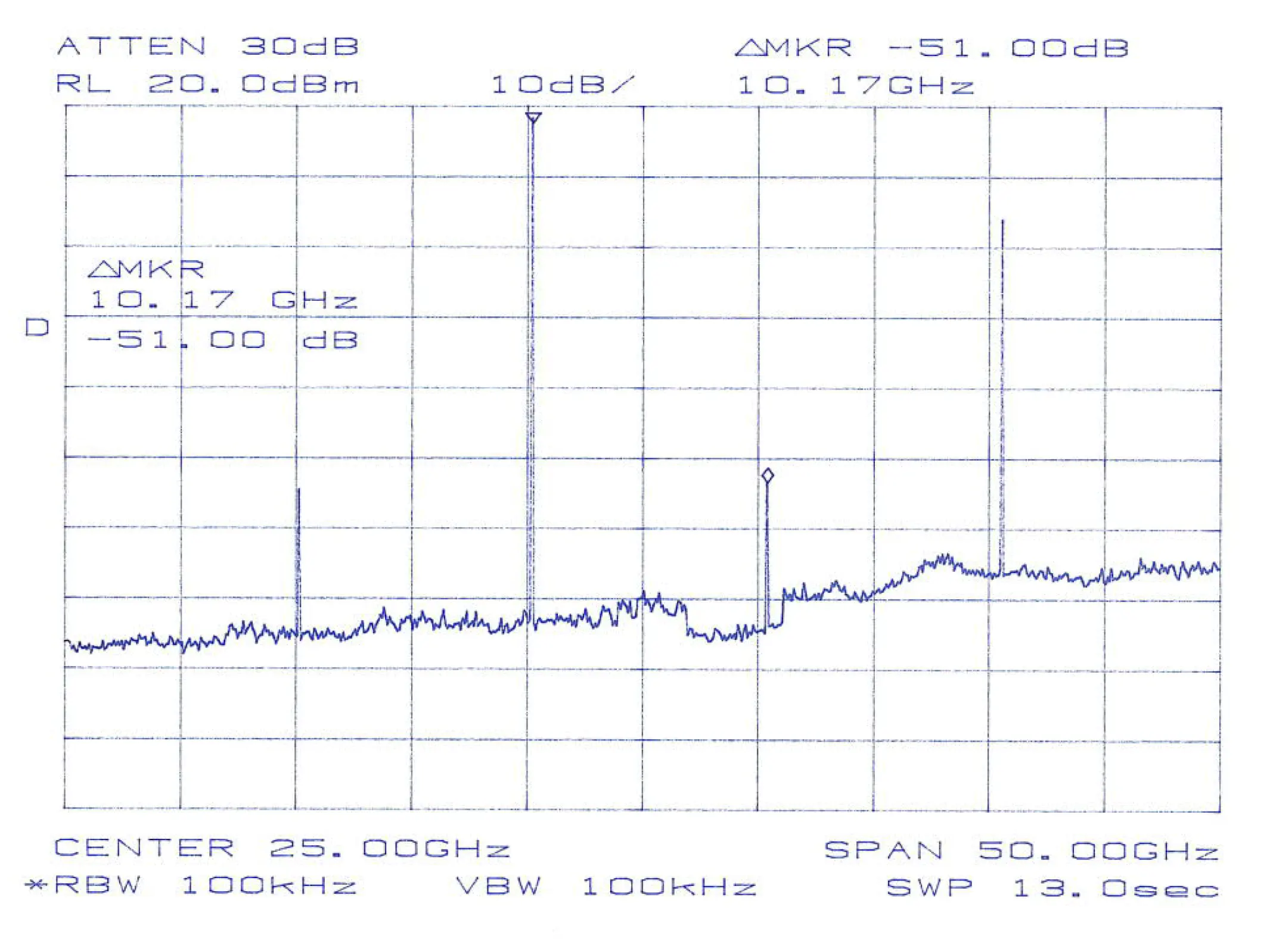
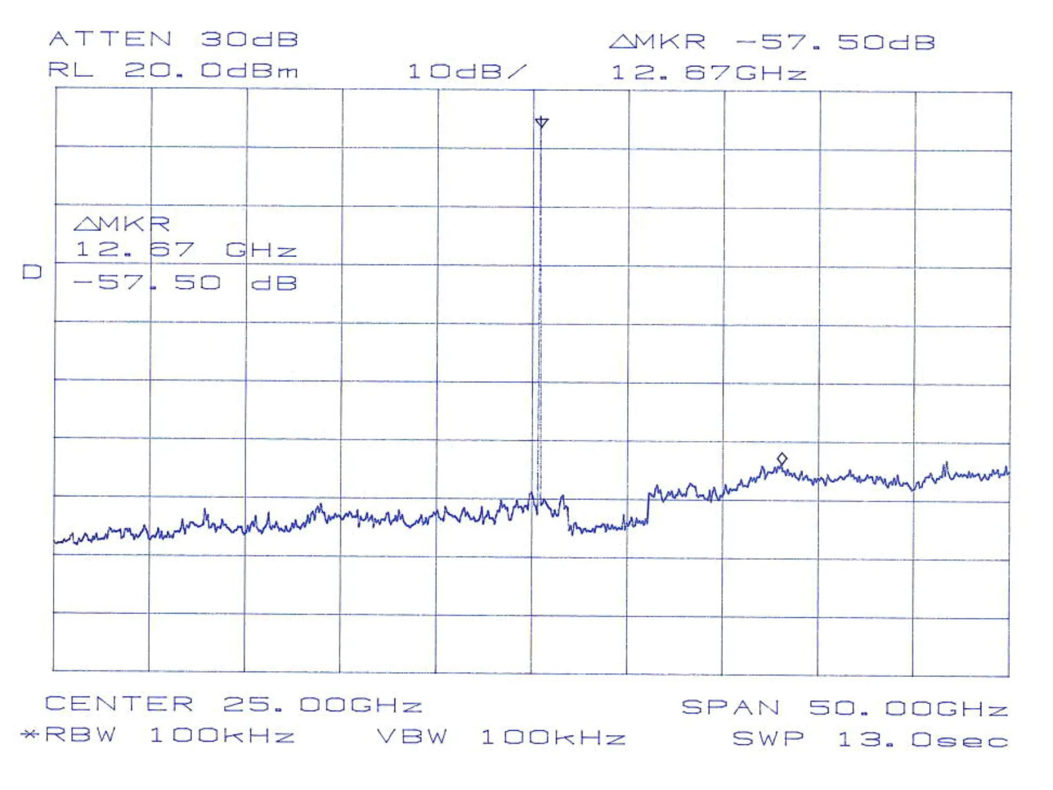
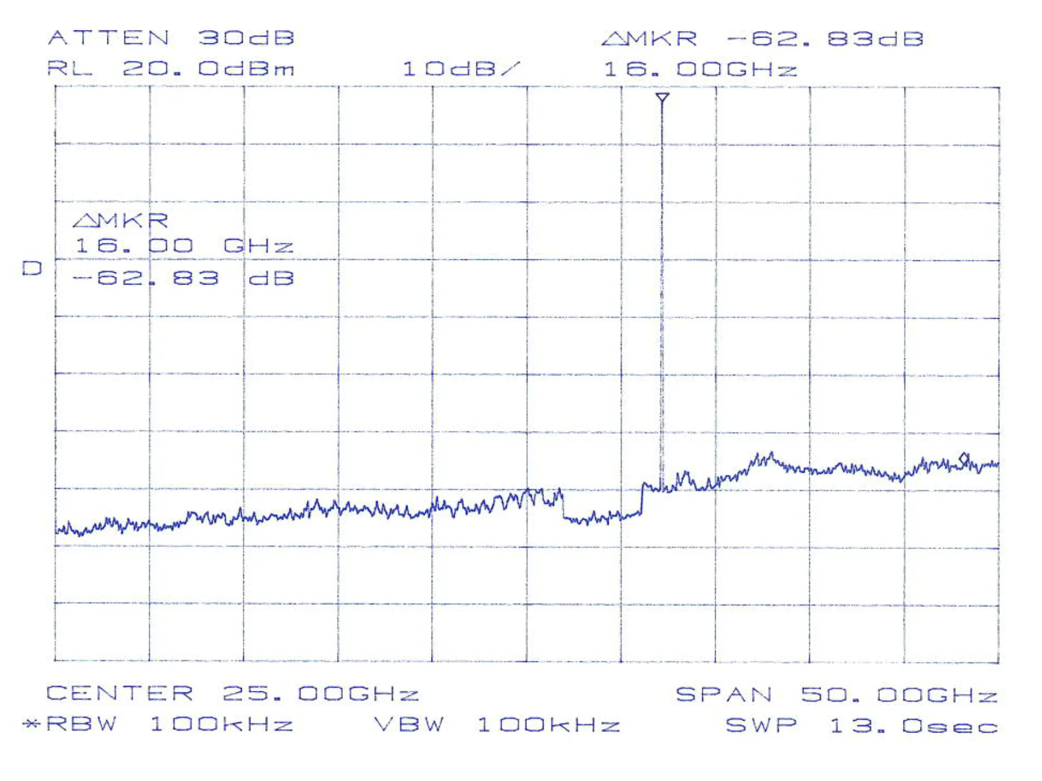
G-MULT-20-40-000
Two-band x2 architecture intended to extend a 10.1-20.0 GHz drive into the 20.2-40.0 GHz region while maintaining sub-harmonic suppression and usable flatness across the published passbands.
| Input | Output | Why this point matters |
|---|---|---|
| 10.1 GHz | 20.2 GHz | Lower-band multiplication checkpoint |
| 12.7 GHz | 25.4 GHz | Band split / transition checkpoint |
| 16.0 GHz | 32.0 GHz | Upper-band mid-span checkpoint |
| 20.0 GHz | 40.0 GHz | Upper-edge output checkpoint |
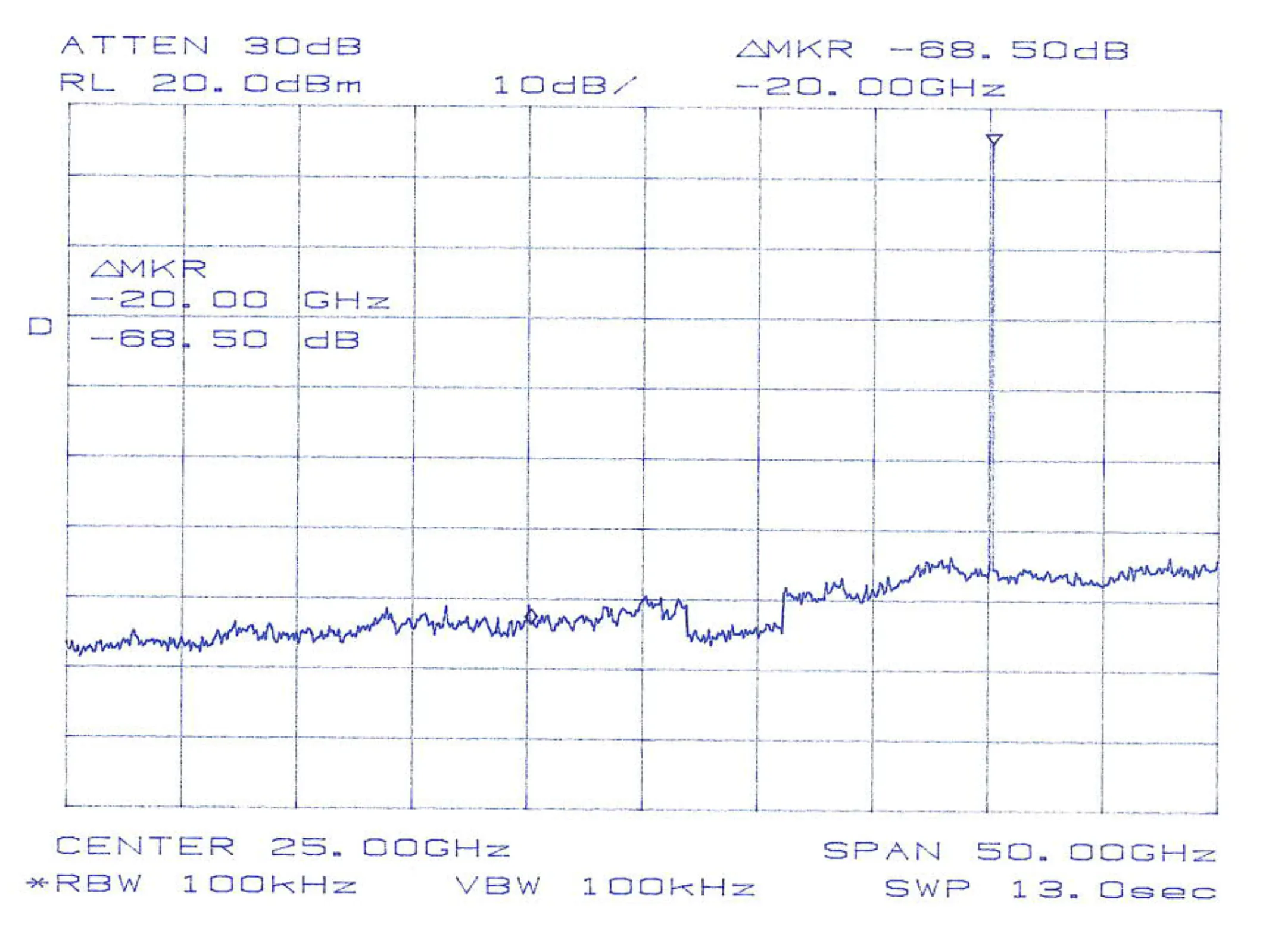
G-MULT-20-50-000
Multi-band x2/x3 architecture used to extend the available output range to 50 GHz, with published checkpoints spanning both doubled and tripled output paths.
| Input | Output | Why this point matters |
|---|---|---|
| 10.1 GHz | 20.2 GHz | Lower-edge x2 checkpoint |
| 14.2 GHz | 28.4 GHz | Upper x2 band checkpoint |
| 14.8 GHz | 44.4 GHz | x3 band checkpoint |
| 16.67 GHz | 50.0 GHz | Upper-edge x3 checkpoint |
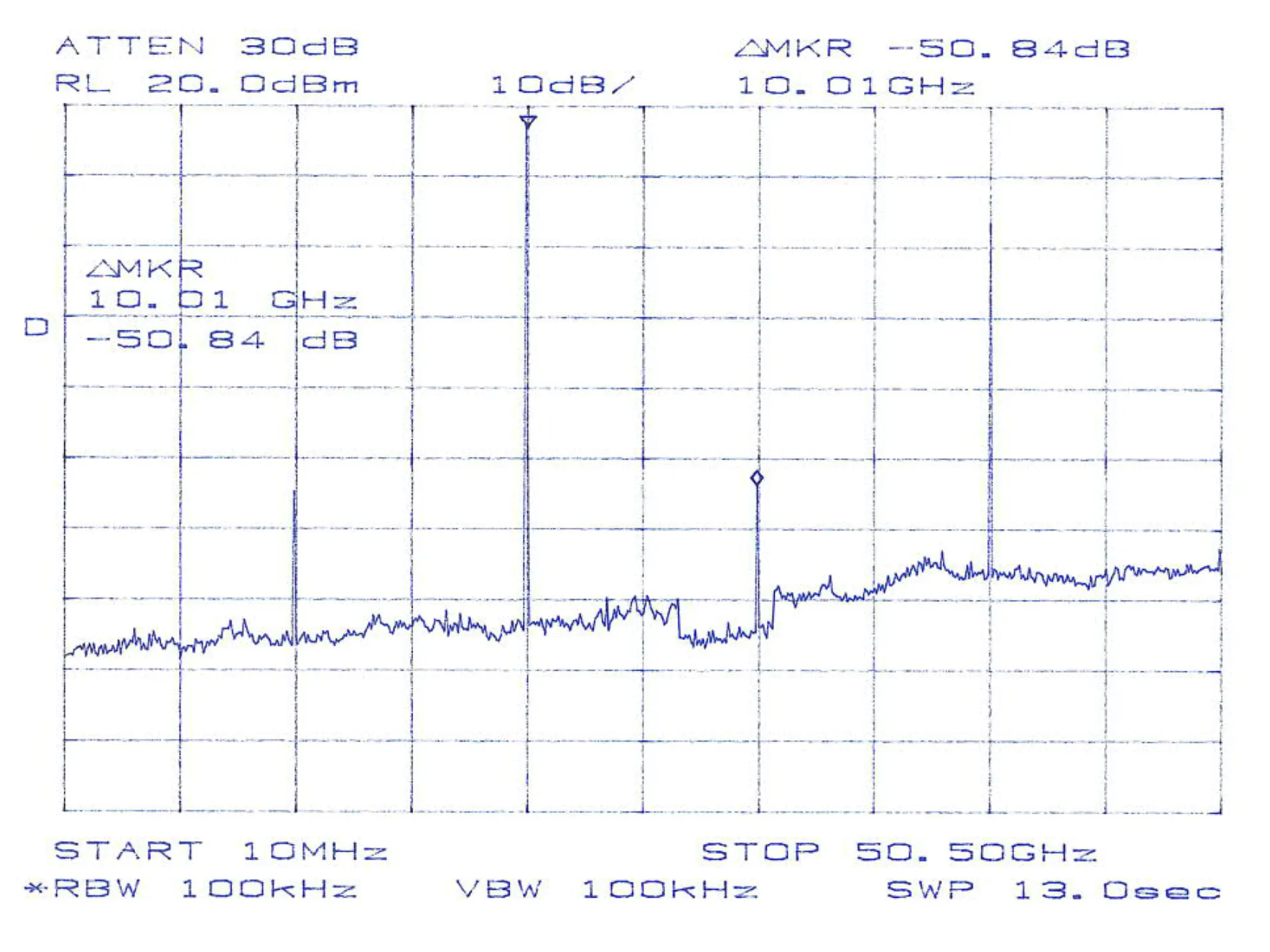
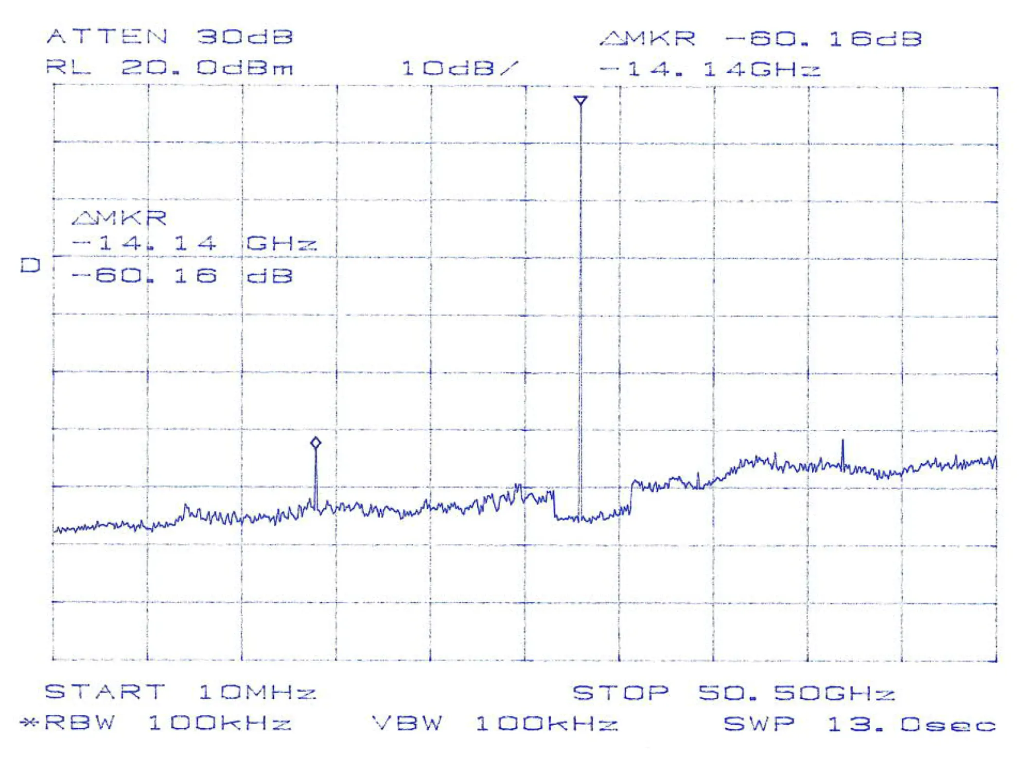
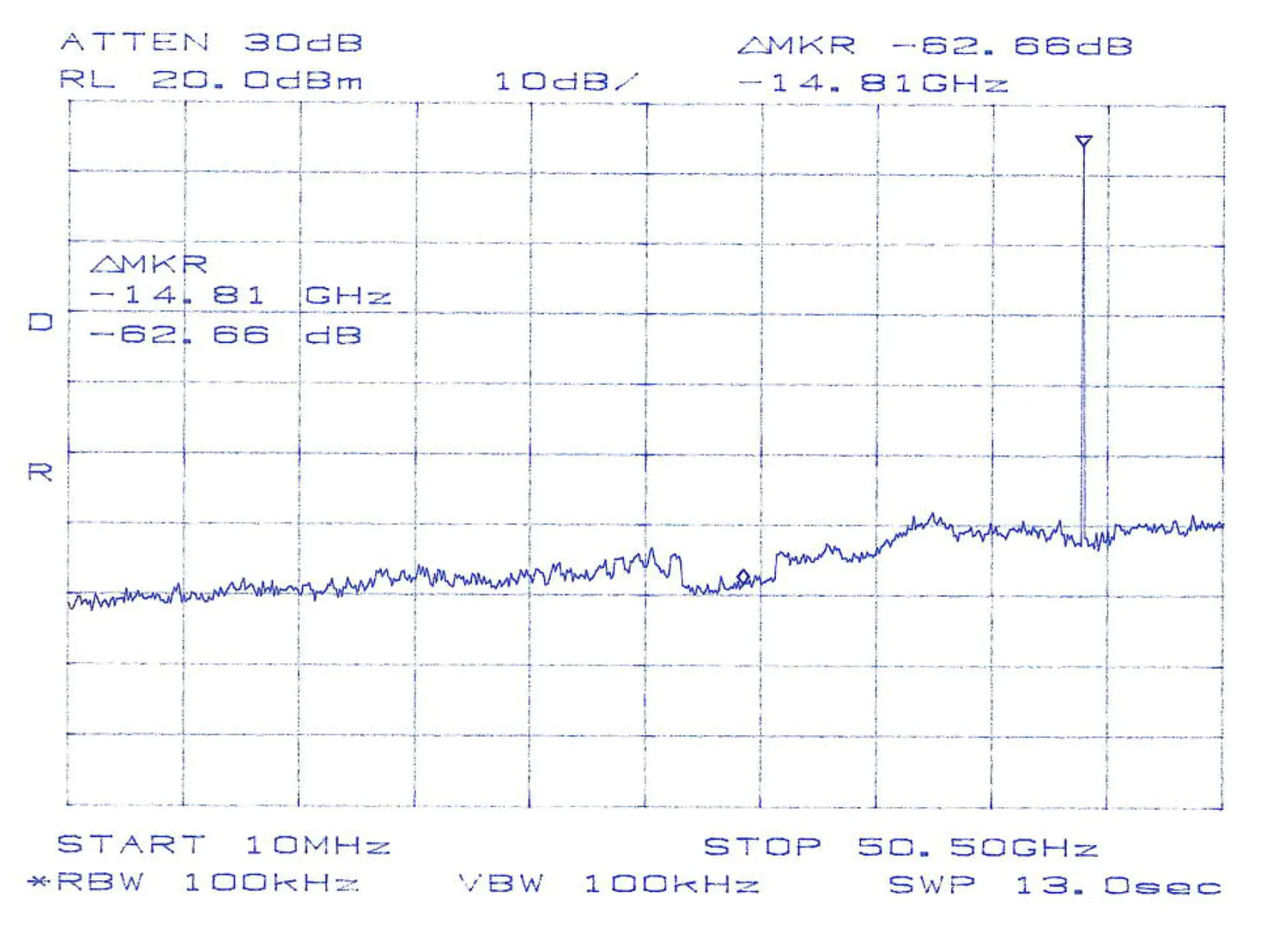
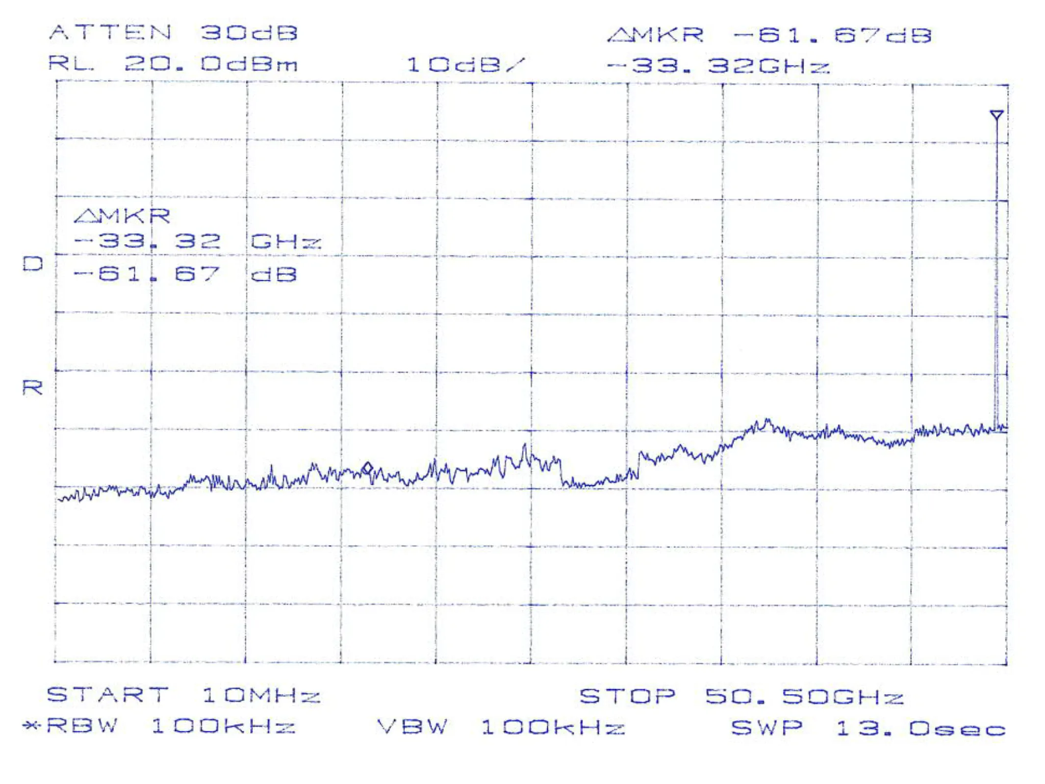
Representative measured output-spectrum checkpoints from the MSI catalog. These plots illustrate sub-harmonic suppression behavior at the published drive and output frequency pairs.
System context
Where frequency multipliers fit
A multiplier extends a lower-frequency source; converters translate bands; filters and amplifiers clean and condition the chain before and after mixing.
Source
A DRO, YIG oscillator, or synthesizer provides a fundamental or tunable tone.
Multiplier
Extends that tone to a higher microwave or mm-wave band for LO or stimulus use.
Converter
Mixers and frequency converters translate to IF or other bands as the architecture requires.
Filter / amplifier
Band definition, spur control, and gain staging complete the path.
Component roles at a glance:
| Component | Primary role | Typical use |
|---|---|---|
| DRO / YIG / synthesizer | Generate the source frequency | Fundamental LO or reference generation |
| Frequency multiplier | Extend frequency upward | Higher-band LO generation and mm-wave extension |
| Frequency converter | Translate between bands | Up/down conversion around a stable LO |
| Filter / amplifier | Condition the signal | Cleanup, selectivity, and gain |
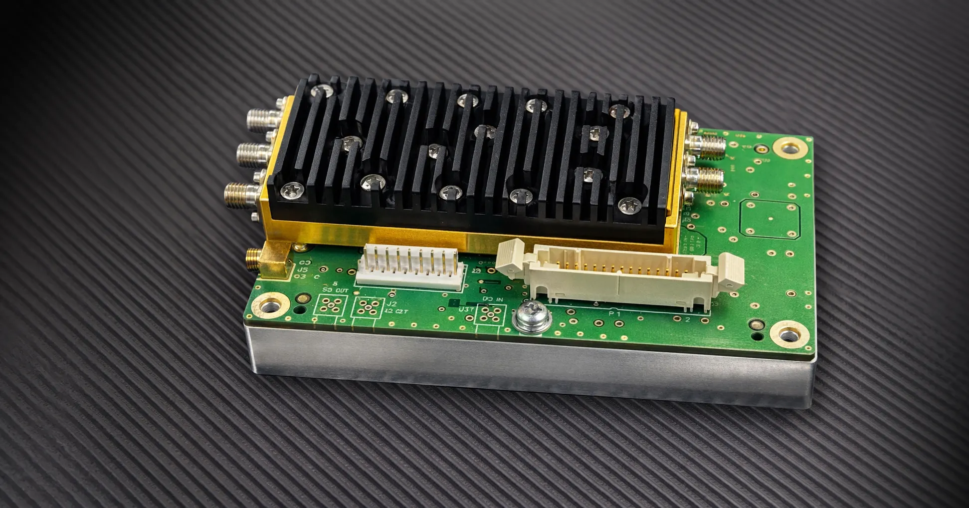
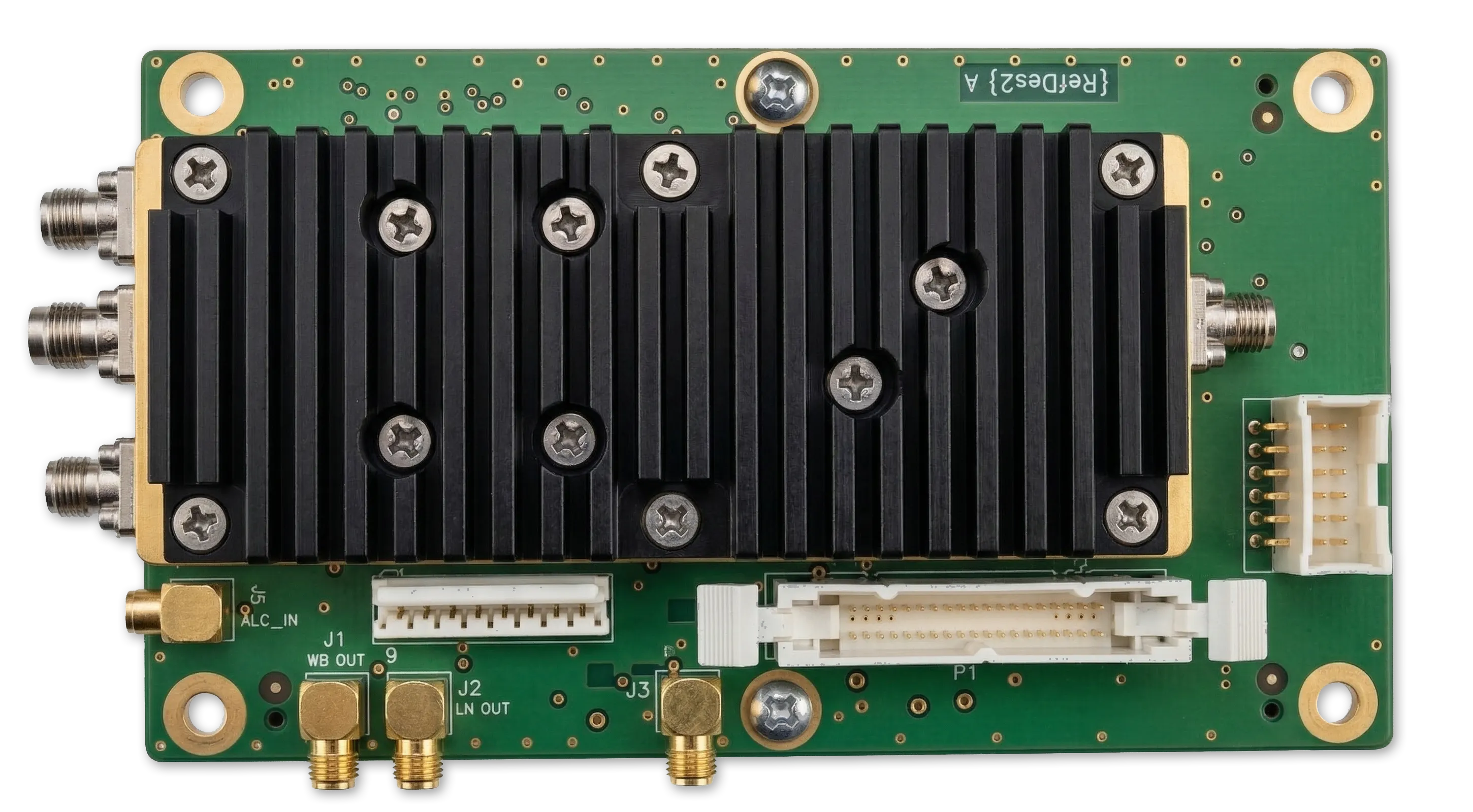
Packaging
Representative packaging and material notes
Mechanical and materials data for G-MULT-20-40-000 and G-MULT-20-50-000—confirm interfaces and finishes on your program documentation.
G-MULT-20-40-000
- Dimensions: 4.40" (L) × 1.59" (W) × 0.76" (H)
- Housing / inner cover: aluminum alloy 6061-T6, soft electroless gold plate over electroless nickel plate
- Outer cover: aluminum alloy 4047, chemical conversion coated per MIL-DTL-5541F
- RF connections: SMA, 2.92 mm, SMPM or equivalent
- DC pins: soft electroless gold over Kovar (Fe-Ni-Co alloy) or equivalent
G-MULT-20-50-000
- Dimensions: 4.80" (L) × 1.59" (W) × 0.76" (H)
- Housing / inner cover: aluminum alloy 6061-T6, soft electroless gold plate over electroless nickel plate
- Outer cover: aluminum alloy 4047, chemical conversion coated per MIL-DTL-5541F
- RF connections: SMA, 2.92 mm, SMPM or equivalent
- DC pins: soft electroless gold over Kovar (Fe-Ni-Co alloy) or equivalent
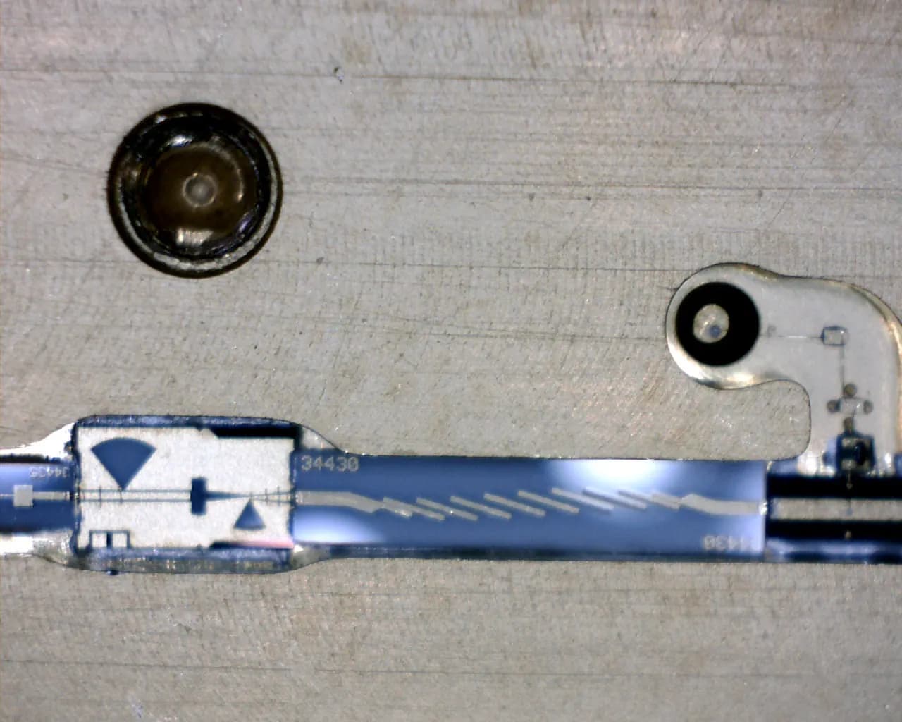
ADVANCED CAPABILITY
Discrete Multiplier Architectures to 50 GHz
Custom harmonic control and high-frequency performance beyond MMIC limits
While most applications are best served by MMIC-based multiplier designs for cost and repeatability, certain high-frequency and performance-sensitive applications require a discrete approach.
Microsource maintains the capability to design and build discrete frequency multipliers operating to 50 GHz and beyond, enabling precise control over harmonic generation, filtering, and spurious response.
This capability reflects deep expertise in microwave circuit design, materials, and high-frequency layout, not just component integration.
- MMIC solutions are unavailable or bandwidth-limited
- Harmonic content must be tightly controlled
- Spurious performance must be engineered at the circuit level
- Custom frequency plans require non-standard multiplication schemes
DISCRETE VS. MMIC APPROACHES
MMIC-Based Multipliers
- Lower cost
- Compact, production-ready
- Fast deployment
Discrete Architectures
- Higher frequency reach (to 50 GHz+)
- Custom harmonic shaping
- Optimized spurious performance
- Greater design flexibility
Why Microsource
Source-chain engineering at system depth
Microsource brings long experience across microwave sources, multipliers, converters, filters, and integrated assemblies—so multiplier choices are made in the context of real LO plans, environmental limits, and interface constraints. We routinely integrate filtering and output conditioning with multiplier cores, and we support harsh-environment packaging, screening, and plating options when programs require them.
Related solutions
Adjacent product families
Multipliers pair naturally with tunable sources and converters in the same signal chain.
- Microwave Frequency SynthesizersProgrammable LO and signal generation subsystems.
- DRO OscillatorsStable narrow-tuning microwave sources.
- YIG OscillatorsWideband tunable YTO-based sources.
- Linear Frequency ConvertersLinear up/down conversion around multiplied LOs.
- Custom Integrated Microwave AssembliesCustom microwave assemblies and subsystem integration.
NEXT STEP
Discuss your microwave frequency extension requirements
Talk with Microsource about multiplier architectures, filtering strategies, and practical high-frequency signal-chain design.